Searching for Stability
Contents
Proposal
Project Description
Overview
Our project is to create a bike-mounted stabilizing platform for iPhone cinematography. We will use the readings from two magnetic encoders to control two motors responsible for stabilizing the platform. Vibration dampening pads in the mounting device itself will provide additional stability. If successful, applications of an inexpensive, compact stabilizing device could be innumerable, from handheld usage to RC and aerial filming and photography.
The mounting device of the gimbal is an original design drafted in SketchUp and produced in AutoCAD.
By the end of the semester we will be able to present iPhone footage from our device to illustrate its stabilizing capabilities.
Team Members
- Natalie Ng
- Nathan Schmetter
- Deko Ricketts (TA)
Objectives
- Program an Arduino module to receive data from magnetic rotary encoders to consistently level the iPhone while in use
- Design and construct a practical and functional mounting device for an iPhone on a bike
- Design and embed the gimbal and additional stability elements either onto or within the mounting platform itself
- Successfully stabilize the iPhone while recording a video from a moving bike
Challenges
- Perfecting the programming of the Arduino module in order to analyze the input from the two magnetic rotary encoders and communicate with the two brushless motors to re-level the iPhone
- Ensuring that input from the encoders is readable to the Arduino
- Identifying appropriate motors to carry out the stabilization of the platform
- Designing the mounting device and modifying gimbal design using 3D printer
- Finding the most effective dampening cushions considering size and weight of platform
- Compacting all elements of the design to create an unobtrusive stabilizing device
Budget
Arduino
- Parts Ordered Online
- Hardware
- 4 9V batteries ($21.99)
- 4 Screws to secure dampening pads
- 3 9V Battery Snap Connectors
- Wire
Total: $90.99
Gantt Chart


Design & Solutions
Modules
Motor Circuit
We began our journey with 3-phase induction motors knowing little else than that they were the best possible motors for generating smooth corrections such as those executed by a gimbal.
1. Direct connection: Our first motor circuit was simple, consisting of the three-phase motor and three wires that fed directly into the Arduino with our laptop as the only power source. Somehow, we managed to make this work without frying anything... Using this circuit we managed to not only get extremely reliable motor control, but also responsive communication between our encoders and our motors. The only catch was that our motors lacked torque.
===>
+


2. Motor Control Circuit I: After bringing our torque dilemma to Humberto's attention, he told us that there was no way our circuit should have been working, as the Arduino was not providing anywhere near the current or voltage we thought it was due to current-limiting. He suggested a completely new motor control circuit including 6 MOSFET transistors as the answer to our torque problems. Despite being warned to watch our connections as we would now be dealing with large amounts of power, we promptly fried our Arduino. Following Professor Gonzalez's roughly drawn schematic, we built the new circuit and again, managed to get a response from our motors, this time using batteries as an external power supply. For the first time, we were able to generate enough torque to spin our phone.
===>


3. Motor Control Circuit II: Though we thought we had been successful, our batteries began to die as the circuit rapidly discharged them. We realized we would need a power supply for the demo, and this is where everything became massively unreliable. Using a power supply, we would get motor control at times and minutes later the motor would be unresponsive to the same code with the same power supply settings. Additionally, a couple of our transistors were getting dangerously hot. Deko suggested that we buy 6 10 ohm, 10 watt resistors in order to get more power to our motors and to prevent our transistors from heating up. While this improvement helped with the heat issue, our reliability issues persisted.
===>
+


.gif)
//Check the functionality of both MOSFET Transistors and Diodes//
3D Design and Printing
When you compare our first design of the stabilization platform/gimbal to our last, many of the differences are blatant. However, in between these designs were many small steps and changes that each addressed a specific issue discovered after analyzing the print of the previous prototype.
- Design 1 was simply a starting point, (Figure 1). It lacked both balance and a mounting bracket for the phone case and was never printed. This iteration helped us realize that we needed a place to attach the vibration dampening pads that would smooth out the video.
- Our second design included space for the vibration dampening pads as well as a place to mount the phone. We realized that mounting the phone with such a high center of gravity would be detrimental to the stability of the platform, (Figure 2).
- Design 3 was the first model we printed, (Figure 3). We quickly realized we needed to re-think clearances because when we rotated the paddle and the phone at the same time, the phone ran into one of the upright supports. This was the first time we were able to assemble the entire prototype, including the motors and the phone. We learned that both the paddle and the phone mount were unbalanced and thus the motors could not produce enough torque to rotate them.
- The balancing process took place before printing our fourth and final prototype and is described in more depth below, (Figure 4) . After balancing, both the paddle and the phone could turn freely within the upright supports. Additionally, we added housing for the encoder that stabilized the base while allowing free rotation of the rotary shaft.

Figure 1: The first prototype lacking a mount for the phone.

Figure 2: The second prototype with a phone mount, battery storage space, and room for the Arduino.
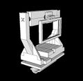
Figure 3: The third prototype displaying a significant design shift in the phone mount & central paddle.

Figure 4: The final prototype, including a counterbalance mounted on the back of the paddle.


On balancing: Balancing the phone was relatively easy. We modified the original phone mount and elongated it so that, when mounted, the phone's center of gravity lined up directly with its axis of rotation, (Figure 5). Balancing the paddle proved much more difficult as we had to take into account not only the center of gravity of the paddle, but also the contributions made by the center motor, the phone mount, and the phone itself. Our original paddle practically fell over and our motor had no hope of rotating it, (Figure 7). While aiming for the same center of gravity alignment achieved with the phone mount, we overcompensated on our second paddle design, which simply fell the other way, (Figure 8). Our final paddle struck a compromise and even gave us some flexibility, allowing us to load varying amounts of weight on the backside to achieve perfect balance, (Figure 9).
A simple test we used to determine if a component was balanced or not was to see if it retained its position after being rotated to any angle.
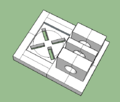
Figure 5: The original phone mount that failed to offset the phone.
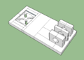
Figure 6: The second and final phone mount that accounted for the center of gravity of the phone.
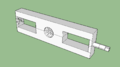
Figure 7: The original paddle that fell forwards.

Figure 8: The second paddle that fell backwards.

Figure 9: The final, balanced paddle with the motor attached along with the screw to mount counterweights.


.png)

Coding
Interrupts on Arduino