Peek-a-Thief
Project Proposal
Overview

What goes on in your dorm room while your away? When you have class and your roommate is home, what do you think he is doing? If you are even slightly suspicious that your personal stash of snacks is being eaten by someone else, then we have the solution for you.
Introducing: Peek-a-Thief, an operating system with the sole purpose of capturing close up images of the people who open up your drawers. Our end goal is to create a security device that discretely captures thieves in action.
Check out the Peek-A-Thief Twitter Feed!
Team Members
- Michael Pichardo
- Derick Speltz
- Will Luer (TA)
Objectives
- Sense a person that opens up your drawer using the HC-SR04 ultrasonic sensors
- Create a sleek operation design that ensures the electrical hardware is hidden
- Create a mobile system that can operate in multiple environments including dorm rooms, offices, etc.
- When triggered by the sensor, take a picture using an 8-Megapixel camera
- Take pictures of a person every second for the first 10 seconds the drawer is opened
- Store picture data locally on Raspberry Pi
- Upload to social media platform (Twitter)
- Stretch Objective: Integrate an Alarm system to startle the thieves!
Challenges
- Design sensor supports (for 3-D print) using SolidWorks software
- Hiding camera, wires, etc. so that they cannot easily be seen from the outside
- Construction: Attach the sensor supports onto the inside of the drawer with epoxy glue and ensuring that the sensors don't interfere with each other
- Environment: Finding a good location for the system to operate in (good lighting for the picture, minimal extra noise that would interfere with the ultrasonic sensors)
- Hardware: Making sure sensors are stable and that the ultrasonic sensors work when sending signals against different types of materials
- Software: saving all picture data on Raspberry Pi to possibly upload to a social media interface
- User Safety: ensure fire safety from electrical system
- Privacy Considerations: In order for our system to work properly, we will need to take a picture of the person by optimizing camera angle. Given that it is surveillance of our own property, privacy of thieves will not be compromised.
- Operation Costs: Our operation does not cost us anything except time, but we enjoy what we do
Budget
- 8 MegaPixel Camera for Raspberry Pi: $25.00 + 7.99 (Shipping Charges) [1]
- 1-meter Flex Cable for Raspberry Pi $3.95 + 9.42 (Shipping Charges) [2]
- Raspberry Pi Charging Cable $5.95 + $9.42 (expedited shipping) [3]
Total Budget: $61.73
Lab Materials / Our Own
- Sterilite 16 Quart Stacking Drawer with White Frame - 17" L x 14-3/8" W x 6-7/8" H (We own it) [4]
- Glue Gun [5]
- Through Hole Resistors [6]
- Male to Male Jumper Cables [7]
- Female to Female Jumper Wires [8]
- One: Medium-sized Stuffed Teddy Bear (We own it) [9] [10]
- Raspberry Pi & Breadboard (Lab) [11] [12]
- Two Ranging HC-SR04 Detector Sensors for Raspberry Pi: (Lab) [13]
- Wires, Cables, Electrical Tape, Soldering Iron [14]
Gantt Chart

![[9]](https://www.dropbox.com/s/aa09pklvjptewag/Screen%20Shot%202017-03-03%20at%203.12.13%20PM.png?dl=0)
Design & Solutions
Module Description & Solutions
Module 1: Drawer
The plastic drawer was a simple module because it was easy to assemble and consisted of only two components (outside structural box and the drawer itself) which fit perfectly together. Despite the simplicity of the drawer, it had to be modified a little to fit the specifications of our project. To support the Teddy Bear module, we had to cut out a rod of wood and connect it to the top of the drawer using hot glue. Additionally, to prevent obstruction from opening/closing the drawer, notches had to be cut in the plastic roof of the drawer. This made room for a GPIO connecting cable between the breadboard (which was on the inside of the drawer) and the raspberry pi (outside of drawer). Further, we carefully measured and cut sheets to drill to the sides of the drawer to hide the wires on the inside of the clear plastic walls.
Module 2: Teddy Bear / Camera
The teddy bear had to undergo surgical operations to ensure it could sit in an upright position on top of the drawer. The wooden rod had to be inserted into a slit on the backside of the bear to keep it from falling during the demo. Additionally, to ensure quality pictures of the thieves in action, the camera had to be placed at an optimal angle inside the eye cavity. To do this, we used stripped wires to attach the camera to the bear fabric while being able to hide the camera discretely. Even then, there was a lot of touching up to do by cutting all the fur around the eyes. This ensured that nothing obstructed the lens of the camera and prevented the user to get a clear picture of the thief.
Module 3: Sensor / Sensor Support
Our goal was to create a system with two HC-SR04 ultrasonic distance sensors to complete the task of detecting whether the drawer was opened or closed. For this, the sensors must be pointed upwards towards the roof of the drawer. So when closed, the sensors would know the distance to the roof of the drawer and not take a picture and when opened, the distance would be greater than the roof, thus passing the threshold distance and capturing a picture. To position the sensors in this way, we had to design identical 3-D printed pieces that would connect to the inside walls of the drawer and we could attach our sensors to these supports. These sensors were glued towards the very front of the drawer so when the drawer is opened, the sensor would immediately identify if it is open, and trigger the camera.
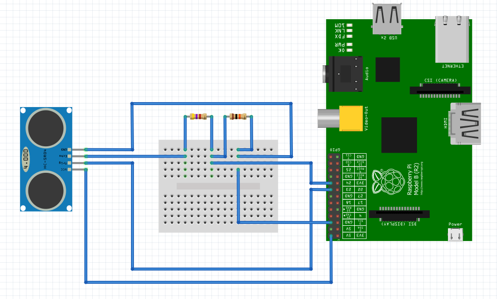
Module 4: Wires & Breadboard
So we didn’t have to attach the breadboard directly to the raspberry pi, we used a GPIO connector. Next, the wiring from the sensors to the breadboard was done by looking at an online diagram which showed where each pin on the sensor should go to on the board and reciprocating the process on the other side to account for a second sensor. Using the diagram, we had to add a 4.7 k ohm and a 10 k ohm specific resistors on each side of the breadboard. The wires provided with the sensors were very small and we had to solder extensions to these so it would reach from the front of the drawer (where the sensors were) to the back (where the breadboard was) Also, to make room for personal objects inside the drawer and ensure its utility, we needed to deal with the wires connecting the ultrasonic sensors to the breadboard. Thus, we bundled the wires together and taped them to the sides of the drawer. The breadboard itself was also taped to the back wall of the drawer so that all wires were stable in place and there was minimal chance for wires to be unplugged from the breadboard.
Module 5: Raspberry Pi
This module was the operation control system of our entire project. Connected to the sensors and the camera, the Pi could use Python code to operate the hardware. We used source code from a project called Feeder Tweeter which used ultrasonic sensors and a camera to take pictures of birds. We had to edit the code to account for having two sensors and our specific project goals. Additionally, the Raspberry Pi stored the pictures we took locally and uploaded these pictures onto Twitter.
HowTo Pages
Results
- Present all your results, including modules that only partially worked.
- Discuss how the results compare to your original objectives.
- Identify the critical decisions or factors in your project that stopped you from getting a better result (try to avoid obvious comments such as "we run out of time").
- Include a copy of the poster you used in your demonstration to help explain your results.