PartyBox log
Contents
1/22 - 1/28
- Group finalized PartyBox project idea
- General objectives: LED array, modular and connectable, response to live music, different modes, wireless (if time permits)
- Wiki page published
1/29 - 2/4
- Group met with TA Nathan to discuss project proposal and demo.
- Developed finer ideas of project (center cube with processor and power, no wireless, only music and standby modes, and modularity with plugs flush to cube surface).
- Drafted and finished a project proposal, including a Gantt chart.
- Agreed upon minimum weekly meeting, Monday at 7pm
2/5 - 2/11
- Met with Nathan and discussed issues with the previously submitted proposal, most importantly the need for an additional arduino on the second cube
- Group meeting on 2/8/17:
- Sketched out a basic picture of what we’re brainstorming
- Add sketch to proposal?
- LEDs 4 x 4 x 4 with none on bottom where Arduino is located
- Reevaluated how we would get the two cubes to connect
- Considered more complicated mechanisms, such as force sensors, but ultimately decided on just wiring the inputs and outputs of the two arduinos together using male/female plugs
- Fix Budget
- Removed items we previously thought we would need (micro-USB)
- Add new objects to connect the cubes
- Physically: Magnets? (Could be too expensive) 3D Print locking mechanism?
- Plugs/wires straight from an output port of one Arduino to an input port of the other
- Specify resistors
- Magnets, microphones, acrylic adhesive, counters, transistors
- Fix formatting of proposal
- Adjust Gantt chart
- More time for physical construction
- More actions occurring simultaneously
- Add more details to the overview in the proposal (size specifications, reason for two cubes)
- Sketched out a basic picture of what we’re brainstorming
- Group meeting on 2/9/17
- Dropped the plan for the second cube due to budget constraints
- Adjusted Gantt chart accordingly to account for the change in objectives
- Finalized budget
- Spruced up project proposal
Lydia:
- continued to research LED Matrix implementations. Used this tutorial
Graham:
- began learning how to operate AutoDesk Inventor and the labs 3D printer
2/12 - 2/18
Meeting with Nathan 2/15/17:
- We do not want to use the battery to power our testing. Therefore, we should purchase a wall adapter that will not take up any power
- We need to add a circuit board to our budget. The lab supplies a prototyping circuit board that we can use for our initial circuit, but we need to purchase a permanent one that we solder our final circuit to so that it does not move while the box is in use.
- After removing the second cube, our project is not as interactive as we would hope. We are considering options to make our cube more interactive, such as the ability for the user to change the light colors.
- For Graham, who is working with 3D printing: Graham should print something very simple and something that we know works with the 3D printer to gain some experience with the 3D printer.
- Graham should also print something with Nathan first so that he can then print without supervision.
- Our objectives need to be formalized some more: mainly, "finished box" is not very clear nor does it give a good explanation of our project. We can get rid of it or explain more thoroughly.
Graham:
- continued to learn Inventor, and began experimenting with suspension structure design
Lydia:
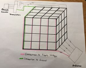
- Worked on concept design for LED matrix
- Five LED sheets running horizontally with each sheet sharing a common voltage supply connection
- Five perpendicular LED sheets would be used for the ground connection
- Identified the following challenges:
- How would the wiring in the corners of where two sides of the cube meet work?
- Is it necessary for the ground connection to be at the top of the cube? Is there a way to keep the decade counter and transistors at the bottom?
- Needed to check with Graham and his design for the structure to resolve these challenges
- How much room would be in the hollow part of the support for the wires to run through?
- Would there be enough room for the wires to loop back down through the support or was there only room for the wires to go one way?
2/19 - 2/25
Group Meeting 2/20/17:
- Nathan suggested 1) addressable LED strips and 2) Bluetooth second cube. However, we ultimately decided not to use either of them -- but we will discuss with Nathan at our meeting on Wednesday.
- 1) Our problem with the LED strips is that they cannot bend the way we want for the design of our cube
- 2) We cannot afford a second cube, as just one cube nearly puts us at budget.
- We decided on a time for our first evaluation.
Meeting with Nathan 2/22/17:
- Nathan told us that we can cub the addressable LED strips and solder them back together, which eliminates our main concern with them. Furthermore, if we were to use these strips, it would take a huge burden off our shoulders as we would no longer have to wire 100+ individual LEDs.
- The LED strips that Nathan linked us to has already been vetted.
- We are not sure how much power we will need for our project (such as, lighting all the LEDs at a reasonable brightness). We can test what power supply we will need with power readouts in the lab, and use those readouts to figure out what our circuit will need.
- In the meantime, we will remove our battery from our budget, but leave a reasonable amount of money for us to buy whatever power supply we ultimately decide on.
- We are still hesitant about our microphone choice.
Group Meeting 2/24/16:
- In researching more about the LED strips and microphone, we have discovered the spectrum shield which will automatically process the data from the microphone we use.
- Group decided to use LED strips and have them light the faces without the inside.
- With the changes to our design, we are need to change our budget:
- We are now getting rid of: the individual RGB LEDs, resistors, gauge wire (we discovered it would be provided by the lab), battery and switch (temporarily, until we finalize our power supply), decade counters, and transistors.
Lydia:
- Scrapped current progress on the implementation of a matrix for the LED circuitry
- Began researching LED strips and how addressable LED strips work
2/26 - 3/4
Group Meeting 2/27/17:
- Edited our Gantt chart to reflect the new tasks that have surfaced with the recent changes in our design (eg. learning how to use the spectrum shield), as well as removed unnecessary ones.
- We found a new microphone that has better reviews than our old one and updated the budget accordingly. We also sent it to Nathan for approval.
- However, the cord of the microphone is 60" long, so there is the dilemma (Sarah's task) of how to place it into the cube.
- Our budget has been approved (except for the microphone), so we decided to begin to order our items: we ordered the LED strips and the spectrum shield + headers.
- We noted that the acrylic casing may not be needed depending on the final design of the suspension structure, but that is something that we can decide later on.
Graham:
- began reworking 3D printed structure because of the inclusion of LED strip lights instead of LEDs
- had first evaluation with Humberto
3/6 - 3/11
Group Meeting 3/6/17:
- Reviewed comments from the first evaluation with Humberto and changed our tasks for this week...
- This week,
- Lydia: The LEDs arrived so she will work with the LEDs in order to be able to control a strip of LEDs to her liking. Also she will see how well she can control the brightness of the LEDS.
- Graham: print the chassis of the cube.
- Sarah: research/look into the videos that Nathan sent us about sound detection and LEDs; create code for button that we can use to switch between modes.
- We established:
- We will remove the "portable and self-contained" aspect of our project objectives, as it is not a key part of the end goal of our project.
- We want to use the diffuser acrylic for the casing of the cube, so that the colors will blend together.
Meeting w/ Nathan 3/8/17:
- The shield we ordered is for an Arduino Uno rather than Mega, which should be fine, but if we need more current for the pins, then we would have to map the pins of the Mega to the shield
- Our ideal microphone should be one that processes and condenses
- We need to start doing microphone work after Spring Break.
- In our design for the box, we could use plastic 2.85mm wire as a pin to hold the box together.
- We should test listening in the music the Lopata Gallery.
Spring Break
No group meetings, just individual work
- Lydia:
- Checked out Arduino UNO
- Began working to understand the LED strips
- Met with Nathan to work on physically connecting the strips to the Arduino
- Cut off pre-attached connector
- stripped the wire
- soldered on piece of metal
- covered in heat shrink for protection
- ClockIn wire to 100 Ohm resistor to pin 13
- DataIn wire to 100 ohm resistor to pin 11
- Used Adafruit_DotStar library to test LED strip.
- Used example program "StripTest" to send 10 colored LEDs through strip, alternating between red, green, and blue
- Noticed comments in example code says that 0xFF0000 corresponds to red, but it actually corresponds to green
- Learned how to control individual LEDs and manipulate color
- Used example program "StripTest" to send 10 colored LEDs through strip, alternating between red, green, and blue
Sarah:
- developed a simple version of the code we will use to switch between modes using a button
- in this case, I am using the button built into the shield of my Arduino, but we will have purchased one for our project
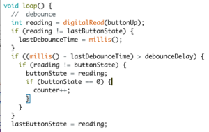
- with the button, I included debounce code that I found from the Arduino website combined with my own previous debounce code, and then added in my own code.
- The general gist of the code is:
- when a button push is detected, increase a variable called counter.
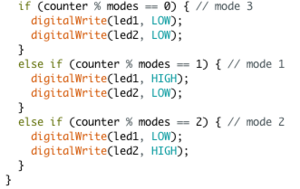
- to determine which 'mode' to be on, or rather, which code to run, I have different if statements.
- I determine which mode to enter by checking what (counter % numberOfModes) is. If it is 1, the it is Mode 1, etc..
- Right now, it is simple code with LEDs; with PartyBox, I could simply make the code in the main loop be a method and have the method for each mode be outside of the loop so it does not clog up the file.
3/20 - 3/26
Group Meeting 3/20/17:
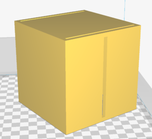
- Graham showed the group his cube shell designs
- We are concerned with wall thickness -- need to test this by printing
- Could connect the LED strips from the separate pieces of the cube using the connectors that came attached with the strips
- Lydia brought in the microphone we ordered over break and discussed her work with LED strips thus far (see individual log during Spring Break).
- Sarah demoed her button debouncing and simple mode switching program, and explained how the code could be used for our end goal (see individual log).
- Goal:
- Lydia:
- Getting exact control of individual LEDs (placement and color)
- Beginning work on patterns
- Graham: print cube pieces
- Sarah and Graham: Attach shield and learn to understand the data from the microphone.
- Lydia:
Meeting w/ Nathan 3/24:
- Soldered headers onto shield to connect to Arduino
- Used example program found on the shield's hookup guide with a phone and speaker
- Discovered that microphone we purchased does not do enough processing to be connected by aux to the shield
- Ordered this microphone which was recommended in the hookup guide for connection to the shield via LGR pins
- We are still unsure how this microphone will work with the shield, but we didn't want to waste any time so we went ahead and ordered it because it is returnable. We are still trying to learn how this connection will work.
Lydia:
- Used FastLED library to control single LED, example program "FirstLight"
- Discovered release of the FastLED library that said it supported the APA102 strip did not actually offer this support. Found later release with bug fix for this issue here
- Note: not every file in the example folder supports the apa102, for example RGBCalibrate
- Edits to standard files in examples:
- NUM_LEDS = 60 (for 1 strip)
- Uncomment line "FastLED.addLeds<APA102, DATA_PIN, CLOCK_PIN, RGB>(leds, NUM_LEDS);"
- Change "RGB" in declaration to BGR
- Learned to use their example colors from this page
- Discovered release of the FastLED library that said it supported the APA102 strip did not actually offer this support. Found later release with bug fix for this issue here
- Discovered that the variable "NUM_LEDS" must be defined to the actual number of LEDs on the strip, though some example programs will define it as the number of LEDs the code is using, or the 13th LED will light up no matter what the rest of the code is doing.
- Learned to make colors cycle through using the FastLED library
- Created file for future use called "3rainbowLEDs.ino" which controls the LED strip as shown below
3/27 - 4/1
Group Meeting 3/27
- Sarah shared information she learned about the lab sound sensor
- Two outputs: analog and digital
- Potentiometer
- Note: goal of brightness being controlled by volume should be scrapped because perceived loudness is not the same loudness as detected by microphone
- We plan to solder leads to the LGR pins on the shield so that we are are able to play around with the microphone breakout board without any permanent attachments to the board
- Overall Goal for week: prototype with processed sound (using phone and speaker)
- Lydia's goal: create several LED patterns to work with
- Sarah's goal:
- (by Wednesday) have understanding of microphone breakout board
- Understand data coming from shield
- Update Gantt chart (lol)
- Graham's goal:
- be able to use frequency bands
- tempo detection with processed sound
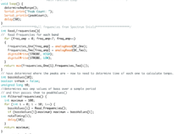
- Done with peak detection of bass frequency (160Hz) bands. Noticed that the bass drum has the highest amplitude in the bass frequency; other bands have equivalent instruments. Will try to create filtered wave and peak detect that wave.
Meeting with Nathan 3/29
- We asked Nathan about connecting the breakout mic board by splitting the mic into two channels, he suggested we try to make it work with just one channel.
- Put ourselves on schedule for 3D printing
- Sarah soldered wires onto the breakout mic and onto the RGL pins on the shield
- We scheduled our second evaluation for Wednesday at 4:30
Group Meeting 4/1
- Finalized some basic details before evaluation next week
- Updated Gantt chart on proposal page
- Updated budget on proposal page
- Updated objectives and project details on proposal page
- Discussed physical aspects of the cube
- Placement of buttons: squish together LEDs on top side, have buttons and microphone fit into the the top of the cube
- Power connection: print cube with a piece of one bottom corner missing to feed wires from power source through so they can be connected to an outlet
Lydia:
- Mapped out LED indices with position on cube
- Began brainstorming patterns:
- Standby pattern: Cluster of three LEDs. One LED in the cluster goes through cycle of red --> blue --> green with an additional brightness cycle. As one LED dims, another LED in the cluster brightens and goes through same cycle. This keeps it so that no more than 1/3 of all the LEDs are turned on to full brightness at once.
- Bottom two lines of LEDs would light up in a dark color upon occurrence of lowest frequency band. Line above those two would light up with a slightly lighter color upon occurrence of second lowest frequency band. Higher frequency bands would correspond with LEDs distributed throughout the rest of the cube. Lighter color --> higher frequency. Higher on cube --> higher frequency. This pattern could be independent of tempo detection or the base color of the LEDs could go through a cycle that cycles at the rate of the tempo.
- Note: Additional problem realized. When tempo detection is working, we will need to decide the conversion between audio tempo and LED cycle speed that makes sense visually
- Stereotypical music visualizer pattern. 6 vertical lines on box would correspond to 6 bands, number of LEDs that light up per vertical line would depend on value of that frequency band
- Note: this would need to be volume in relation to the other frequencies, otherwise all the bands would have roughly the same number of LEDs lit up
- Because it is difficult to really create a pattern without input from the microphone, began working on basic patterns that will most likely be used in more complex patterns with input from shield
- Created pattern that will consist of horizontal stripes rolling down cube when the LEDs are arranged properly
- Used example code in the shield's hookup guide but adjusted the code to work with the LED strip instead of the normal LEDs
- Used second example code, which was supposed to adjust brightness of LEDs
- Brightness is not very noticeable on the strip, so instead had the magnitude of the output from the bands contribute to color
- 0 - 100: off, 100 - 400: green, 400 - 800: blue, 800+: red
- With normal-low volume, all of the LEDs are green
- Lowest LED does not light very frequently in most songs
Graham:
- began work on understanding processed data with shield from the 160Hz band.
- Created filtered wave and attempted to implement peak detection. However, verifying the accuracy of the program proved too cumbersome (had to graph the frequency values in excel).
- Began editing sketch to find the start and stop times of these peaks, rather than count them.
4/3 - 4/9
- No group meeting this Monday because neither Lydia nor Sarah would have been able to make it
- Goals:
- Lydia and Sarah: Connect microphone breakout to shield and understand data
- Graham: Continue working with tempo detection
- Lydia: Be able to rank which pitch is the loudest and apply this information to the LED patterns
Lydia and Sarah:
- Started working with the microphone!
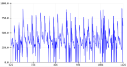
- Connected microphone to shield and read values of "Frequencies_One" and "Frequencies_Two" under varying conditions
- Connected audio output pin from microphone to right audio input pin of shield. Connected ground on microphone to ground on shield. Both "Frequencies_One" and "Frequencies_Two" returned values around 40-50, regardless of external noise
- Considered that maybe we had wired it incorrectly and connected both the ground pins to Arduino's ground. "Frequencies_One" and "Frequencies_Two" both returned values now around 100, independent of environmental sound.
- In a properly working system, "Frequencies_One" should be outputting 0 because it corresonds to the left input, which we left empty. "Freqeuncies_Two" should be varying between 0-1024 depending
- Tested to make sure microphone was working properly to rule that out as a reason for the shield data
- See Oscilloscope gif: the amplitude of the voltage detected by the oscilloscope changes when the microphone detects sound - this verifies that our microphone is working
- Because the microphone is working, why isn't the shield giving us reasonable data? Looking into possible hookup errors and code errors by looking through shield documentation and tutorials such as this or this
- Connected microphone to shield and read values of "Frequencies_One" and "Frequencies_Two" under varying conditions
Lydia:
- Designed light pattern to work with 3 dimensional cube and audio from a phone to begin working with the 3 dimensional patterns
Graham:
- Continued work with tempo detection. Finished a first version of tempo detection with a processed signal from a cell phone.
- Worked to reduce audio data lost while the Arduino performs other functions.
- Began working with the microphone rather than a processed sound signal.
4/10 - 4/16
Goals:
- Lydia:
- create code that ranks frequency bands relative to each other
- create three dimensional pattern with input for tempo
- Get rid of delay() calls in existing code to make sure the Arduino can keep reading the microphone data while the LEDs are being lit
Group:
- Lydia and Sarah soldered extensively
- The copper connections on two LEDs were broken while trying to remove solder
- Will need to make printed cube larger so that there can be support for the soldered joints. The soldered joints are extremely fragile, especially the copper pieces that are part of the actual strip itself
Lydia:
- Did successfully write code to rank frequency bands
- However: these rankings do not perfectly follow the sound perceived by people
- Ranking system can be applied to future patterns, but not directly. It will take more processing
- Created a gradiating pattern across one side of the cube
- Has input for tempo (variable "interval" can be changed depending on the tempo, and the pattern will go faster or slower)
- Still to be done: make colors depend on pitch, add glitter pattern that Sarah is working on, extend to full cube
- Was able to get rid of delay(50) in loop() that was leftover from setup code. Replaced it with a function dependent on millis() in the code that actually animates the LEDs
- Previously thought they delay was necessary to give the shield time to read the data. This is not the case.
Graham:
- Revised tempo detection.
- Fully functional with the microphone.
- Now losing only 5% of total audio data.
- Began work on detecting whether music is playing.
- Using the average amp of the bass band and a threshold to determine the difference between regular ambient noise and music.
- Introduced finite state machine to the code to switch between music and standby mode.
4/17 - 4/23
- Both halves of cube are now printed
Lydia and Sarah finished soldering all the LEDs for the larger half of the cube and they were functional. This process took about a week longer than anticipated because the copper connections on the strips are extremely fragile and tear easily and do not always survive having solder removed from them. It was a frequent battle of soldering more LEDs on and then repairing previously soldered LEDs. We assumed that once we were able to have the LEDs supported on the cube, this would no longer be an issue because we would be able to support the soldered joints with the plastic. However, attaching the LEDs to the cube was more difficult than we had accounted for. While attempting to attach the strip to the cube, a short circuit was created by one of the loose pieces of copper on the strip that damaged several of the LEDs already attached to the cube. It was concluded that the current 3D model was not viable, and that attempting to attach the rest of the LEDs would only damage more and take up an insurmountable amount of time. To resolve this issue, the 3D model was adjusted. The model will now be a cylinder that is sitting on top of a small box containing the Arduino and all of the circuitry. The cylinder will be hollow and allow the user to place a small portable speaker inside, for the purposes of the demo, this speaker will by one that Lydia owns. A diffuser case will fit over the cylinder in the shape of the rectangular holder for the Arduino, which still gives the display a "box" shape. By using a cylinder, soldering is no longer an issue. The LED strip will be able to smoothly wrap around the cylinder and not require additional soldering.
For the new design, the pattern code will have to be adjusted quite a bit. However, none of the other tempo detection code or code involving the buttons will need to be changed at all. The rest of the time before the demo will be spent creating the new 3D model and adjusting the patterns accordingly.
Graham:
- Redesigned the chassis of PartyBox to accommodate the single, uncut strip of LEDs, as well as the bluetooth speaker.
- Revised music detection
- Used more frequency bands to determine if music is playing since the difference between ambient bass volume and music bass volume is slim.
- Tweaked threshold values while testing with and without music to best determine the difference between music and noise.
Lydia:
- Began editing patterns to fit with a cylinder instead of a cube
- Had to make the patterns a lot more simplified since there was not much time left to work with them
Group began compiling all code onto one file to make sure the separate pieces would work together. No major issues were discovered.
4/24 - 4/30
- Assembled all the pieces of the PartyBox
- Connected LED strip to external power source
- Debugged tempo detection with patterns and the music recognition
- Printed poster
- DID THE DEMO
- Began adding work to the wiki
- Created two tutorials, using the FastLED library and using the spectrum shield
5/1 - 5/7
- Finalized the wiki

