Holograms At Home Log
Jump to navigation
Jump to search
Contents
1/29/17
- created first draft of the project proposal.
- explored alternate project possibilities, including displaying just on a cylindrical surface, removing inner led display volume, and making the display scalable.
- considered which components to use, settled on the stepper motor.
- considered using individual LEDs or strip LEDs, and settled on individual LEDs to ensure LED can be individually controlled and visible from multiple angles.
2/7/17
- switched LED to addressable LED strip due to limited number of ports on the arduino
- tentatively decided on about 10 layers of LED
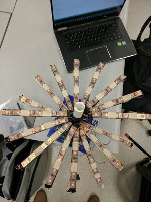
- designed pole, arudino and battery layer, and first LED layer
- 3d printed designed layers
- modified project proposal
- redesigned pole to be hollow so wires can be held inside the pole
- redesigned layers with tolerance on connecting parts
2/14/17
- ran test on the strip LED with Arduino mega, confirmed that each light can be controlled individually
- determined that motor controller and separate arduino was required for motor, and added components to the budget
- arduino battery layer failed to take into account the size of the ports on the arduino mega; fixed design and reprinted
- 2nd LED layers printed
2/21/17
- finalized budget: switch from AA to D batteries, switched to buying 3 led strips, removed wires and electrical tape from budget
- tested motor, torque and rpm too low. Possible cause is 9v is too low.
2/28/17
- got motor speed to around 10 Hz with 24v 2amp power source
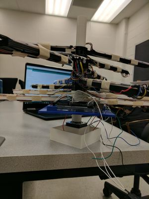
- wired led strips, mounted to frame, and powered Arduino Mega with 9v battery
- programmed Arduino Mega to display semicircle on first layer at around 6Hz
- printed base for the motor
- added hall effect sensor and magnets to budget
3/3/17
- Tested the Hall Effect Sensor for more accurate display time (at low speed and high speed)
- Coded Arduino functions to display LED more accurately using the Hall Effect Sensor
- Wired the second layer of the display
- Discussed the work flow over the Spring Break
3/20/17
- mounted led to 2nd layer of device
- printed 3rd led layer
- printed 4th led layer
- motor driver burned out during motor test
- began coding for controlling device
- created library for images using 3d arrays
- created algorithm for displaying spheres with varying radius, xyz offset, color, and duration of display
3/27/17
- created library for displaying cylinder with varying radius, xyz offset, color, and duration of display
- created library for displaying rectangular prism with varying sizes, xyz offset, color, and duration of display
- designed protocol to switch lights on strip based on angle of display device
- printed layers 6,7,8
- wired leds to layer 6,7,8
- wired hall effect sensor
- completed physical assembly
4/3/17
- ordered replacement motor driver
- Arduino code took up too much memory
- looked into solution to memory issues with code, two possible solutions: using vectors to selectively store necessary data (lights that are on), or keeping only one 3d array (containing which lights are supposed to be on at different angles for specific images) as a global variable and modifying it as necessary
4/13/17
- printed connector to attach pole of device to the new motor
- uploaded code to the arduino to control new motor controller
- attempted to use broken LED stand as frame for device, the stand was not rigid enough to withstand the vibrations caused by the motor
- designed frame to attach motor to device to be 3d printed
- designed frame to be made out of wood in case 3d printed frame is not sufficiently stable
- began working on the poster
- printed frame to connect motor to the frame
4/20/17
- soldered led layers
- finished building frame
- finalized poster

