Accelerometer + Pi Zero
Revision as of 14:59, 22 April 2019 by Huther (talk | contribs) (→Wiring the Accelerometer to Pi Zero)
Overview
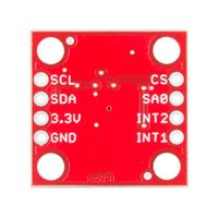
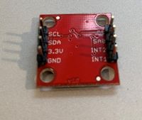
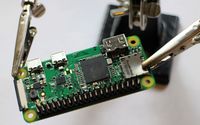
Module 1 of our project involves wiring the H3LIS331DL accelerometer to the Raspberry Pi 0, as well as implementing the code in python that executes the readings. This specific accelerometer is 3-axis, meaning it records data in the x, y, and z-planes, and can take readings up to +-400g's. Once the sensor was wired to the pi, we had to code the pi to use the sensor, specifically GPIO pinouts.
Materials
- Raspberry Pi Zero
- H3LIS331DL accelerometer
- Headers to solder
- Connector wires
Wiring the Accelerometer to Pi Zero
- Step 1: Solder header pins onto both the accelerometer and the pi (if not already attached).
- Step 2: Wire the Pi to the accelerometer as shown in the following diagram. IMPORTANT: The shape of the accelerometer is slightly different, but the pins still go to the corresponding ports (e.g., GROUND will still go to GPIO pin 9). Additionally, instead of VCC, connect to the 3.3v port on the accelerometer. Also ignore the LED, we will not be implementing it in our final product.
- Step 3: Code on Pi. Open up the Pi (either SSH or on a monitor) and use this link [1] to import code. Once a file with the code has been made, change the maxScale variable to 400, as well as every instance of 6, 12, and 24 to 100, 200, 400 (respectively). For example, if you see RANGE_6G = 0x00, change it to RANGE_100G = 0x00, and so on. Finally, ((((((TO-DO))))))(function to send data to server)
- Step 4: Build case for pi-accelerometer system (((((TO-DO)))))))
- Step 5: Place in headband (((((TO-DO)))))


