Smart Blinds
Smart Blinds Weekly Log
Presentation
Codes and design
Poster
Contents
Proposal
Overview
The goal of this project is to create a set of blinds that is able to automatically adjust the tilting angles of the slates with real time luminosity. The blinds will also feature an timing function which will drive the blinds to open and close at certain time according to user's preference. The apparatus will contain a stepper motor to open the shades and an Arduino processor will be incorporated to measure the luminosity. In order to achieve the project goal, data obtained by the Arduino sensor will be processed and transmitted to the step motor. A temperature sensor will also be added to obtained real time temperature input, so that our device will more accurately adjust its functions. Besides, a user interface containing a LCD display and five bottoms will be incorporated to show the luminosity and the temperature and to let users to open or close the blinds as needed.
If time allows we will add these additional features:
- timing functionality
- design the control mechanism to work with a variety of blinds
Team members
- Xinquan Liu (Toby)
- Sam LaSota
TA: William Berndt Parkinson
Objectives
Electronics and programming
- Find the position to place the temperature and luminous intensity sensor so that it will yield the most precise feedback
- Program the Arduino to obtain the correct inputs of temperature and luminous intensity
- Analyze the data obtained and filtered the noise in the signals
- Transform the inputs of temperature and luminous intensity to proper outputs to the stepper motor
- Analyze the data obtained and filtered the noise in the signals
- Make sure the stepper motor interact correctly with the Arduino
Mechanics
- Build the frame and the blinds
- Connect and test the stepper motor on the blinds
- 3D print parts needed for connection
- Find the correct tilting angles with regard to solar zenith angle
- Adjust the stepper motor to obtain the right tilting angles
- Make sure the right connection between step motor, power source, transistor, and the Arduino
- Visually appealing setup
- Save energy as much as possible
Challenges
- Build the frame and fit in the blinds
- Learn the basis of stepper motor and its connection
- Generate enough torque to tilt the slates
- Adjust the output of motor to gain the right angle
- Find the correlation between the temperature, luminous intensity and the proper tilting angle of the blinds
- Probably will require many experiments and tests at different times of the day
- Program the Arduino to collect and process the data
- Collect precise and enough data to determine the output from Arduino to the motor
- Filter the noise in the data so that the motor will only function when needed
- Transform the input data to the right output signals and transmit them to the motor
- Translate stepper motor torque into blind control using 3-d printed parts
Budget
- Achim Home Furnishings 1-Inch Wide Window Blinds, 24 by 64-Inch, White $11.99 (provided)[1]
- Motor and Driver $8.59 (Amazon)[2]
- 28BYJ-48 DC 5V Stepper Motor
- ULN2003 Driver Test Module Board
- 28BYJ-48 DC 5V Stepper Motor
- Arduino Uno $17.99(Provided)
- Digital Light Intensity Sensor Module for Arduino UNO $5.99[3]
- 8RGB LCD Shield Kit w/ 16x2 Character Display(for user interface) $23.95 [4]
Total: $38.6 (Actually spent)
Gantt Chart
Design and Solutions
Mechanics
The first step to achieving our goal of controlling the blinds with the stepper motor was to build and assemble the components properly.
- Building The Sensor
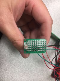
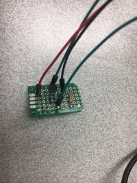
- The light and temperature sensor was built using a simple circuit shown here
- Soldering the connections was straightforward
- Assembling The LCD Shield
- The assembly of the LCD Shield was a matter of following the Adafruit guide
- Soldering the connections was a lot more involved and required a decent amount of time
Programming
The device is controlled by an Arduino Uno Board. The programming of the the device consists of three parts 1)The reading from sensors 2)The control of the motor 3)The control of the display.
Sensor Readings
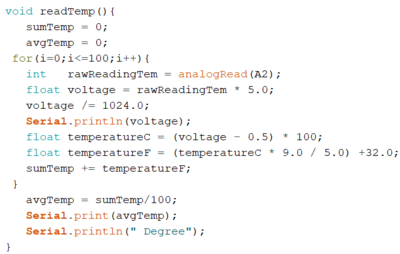
The luminosity is measured by the photo-resistor, from which the function will read the analog input and convert to the correct voltage reading. Then based on the linearity of the photo-resistor measurement, the function uses a scale of 0 to 9 to describe the luminosity, with 0 representing complete darkness and 9 representing full daylight. The temperature sensor(TMP36) utilizes the same overall method but the voltage is converted to a more accurate result in Fahrenheit unit. In order to measure the real time temperature and luminosity more precise, both temperature and luminosity sensors will take in 1000 readings over a period of 3 minutes and use rolling average to filter out the extreme readings caused by noises in the system.


Motor Control
The devise uses 28BYJ-48 Stepper Motor with ULN2003 driver(The complete tutorial and library can be found in the reference). The driver and the library allow us to set the maximum speed of the stepper motor and its acceleration. The moveTo() function will set the stepper motor to the desired location in radians, with 4096 steps a full rotation. The distanceToGo() function allow us to monitor the current state of the motor and to decide when the motor has stopped running. With several trials, we found the correct location of the stepper motor, which corresponds to the angle of the slates of the blinds. After, the reading of temperature and luminosity is complete, the program will set the motor to a certain location to control the blinds, based on our experiments before.
User Interface and Display
For the display and user interfaceRGB LCD Shield Kit w/ 16x2 Character Display(The complete tutorial and library can be found in the reference). The user-interface consists of a LCD screen and five buttons. Our program mainly uses the up and down buttons to open and close the blinds. The display is also used to show the temperature and luminosity. The function for the user interface in the program is userControl(), which is operated during the ten minutes interval between each reading of temperature and luminosity.
Electronics
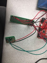
Our temperature sensor and photo-resistor are soldered on a perfboard so that it takes less space and can be easily placed near the window. Also, the temperature sensor and photo-resistor are on the different side of the perf-board, so that temperature will not be greatly influenced by the direct sunlight. All the electronics parts are connected through the another perf-board to the Arduino processor. We use a external 5V power supply to provide electricity for the kit.
Challenges
Like any other engineer in history, our team faced several setbacks and challenges in our project, but we successfully conquered them and learned many new skills during the process.
- In our original design, the motor was connect directly to the shaft in the blinds. However, after several trials, we found that the motor cannot provide enough torque to turn the shaft. As a result, we designed another mechanical set and connect it to the gear set on the blinds, so that the motor is strong enough to turn the blinds.
- In our original coding, the arduino is reading temperature and luminosity simultaneously, which cause one reading interfere with the other because arduino uno only has one ADC channel and it is multiplexed in practice. The analog read cannot process two input within a short time. To solve this problem, we separated the two reading functions so that the readings will be consistent.
- The power supply has been a problem for us throughout the project. Normally, the arduino board and other electronical parts are powered by the USB port, which is connected to a computer. However, putting a laptop near our device all the time is impractical, so we use an external power, which is a modified phone charger. The electricity goes in the the VIN pin on the board to power our device.
- Both stepper motor and the display draw a large amount of electricity, so when they are running together, they might behave inconsistently. To solve this problem, we put the stepper motor in parallel to the rest of the circuit and the display will be turned off when the stepper motor is operating.
To tackle the challenges and the problems we met in the project, we learned several new skills:
- Soldering and some circuit knowledge
- Aruidno C language
- CAD design and 3D printing
- Wiki page editing
- Stepper motor control and LCD display control
Results
Our project fulfills all the objectives in the proposal. The temperature sensor and photo-resistor will measure the temperature in the room and the luminosity of the light coming into the window. The results will be shown on the display. Then, based on the readings, the motor will move to the designated location in radian, which will turn the slates of the blinds to a desired angle through our gear set. However, our secondary goal, which is to create a set that will fit in every blinds set in the market, is not achieved because of the time limitation.

Potential Project Extensions
- Improve the power supply and the stepper motor power, so the the motor can turn faster and thus close and open the blinds more quickly.
- Improve the overall circuit connection, soldering,and layout the the device, so that the device can take less space and can be easier to debug.
- Create an adjustable mechanical set which can fit most blinds in the market.
- Add a timing or clock mechanism to the devise.
References
Motor Tutorial and Arduino Library
User Interface Tutorial and Arduino Library
A project from before: Sunlight Alarm


