Smart Blinds Weekly Log
Jump to navigation
Jump to search
Project page: Smart Blinds
Week 1
September 11
0.5hr Sam
- Created a wiki page.
September 12
1hr
Sam and Toby
- Met with TA Will
- Learned the basis of wiki.
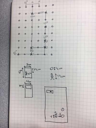
- Studied the circuit and built the night light on the breadboard.
- Discussed the material needed for the project.
September 14
2hr Toby
- Created a proposal draft
2hr Sam and Toby
- Met with TA Will
- Finish soldering Night Light on perfboard
- Discussed proposal
- TA gave advise on the proposal
Week 2
September 18
2hr Sam
- Created budget
- Created Gantt Chart
September 19
0.5hr Toby
- Finished the proposal before meeting with the instructor
2hr Sam
- Finalized Gantt Chart and material list
0.5hr Toby and san
- Meet with TA and instructor
September 21
2hr Toby
- Finalized proposal based on instructor's advice
- Created a presentation power point
Week 3
September 24
3hr Sam
- Started to learn Onshape
- Designed rough draft of night light case
September 26
1hr Sam
- Updated Gantt Chart
1.5 hr Toby
- Looked for user interface and AC/DC convertor online
- Updated budget and presentation
September 28
2hr Sam
- Learned additional Onshape techniques
- Finished Night Light Case
Week 4
September 30
2hr Toby
- Ordered material online
- Reviewed programming for Arduino
- Learned the code of Arduino to stepper motor
October 2
1.5hr Sam
- Researched onshape design techniques for fitting parts
- Exported Night Light case stl file
October 3
1hr Sam and Toby
- Met with TA Will
- Discussed the Arduino programming of photo-resistor and stepper motor control
October 5
2hr Sam and Toby
- Built the circuit for stepper motor and photo-resistor
- Wrote codes for Stepper motor and photo-resistor separately
- Succeeded in turning on the stepper motor and reading inputs from the photo-resistor
Challenges:
- The purchased photo-resistor did not provided desired inputs, so our team built a simple circuit containing a photo-resistor
- Need to find the correct delta timing for photo resistor reading in Arduino coding
- Need to figure out the codes for stepper motor in order to achieve desired effects
Week 5
October 7
1.5hr Toby
- Wrote codes to gain the correct outputs of photo-resistor
- The arduino will read 100000 inputs over a time interval of about 3 minutes and calculate the average of the total inputs
2hr Sam
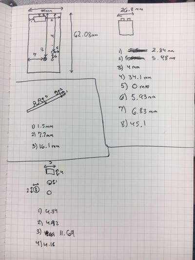
- Took measurements of blind components and stepper motor
- Created a preliminary design of motor to blind connection
October 8
3hr Toby
- Met TA Will
- Found a more useful arduino library for the driver online
- Figured out the functions of the codes
- Able to turn on the stepper motor for a desired number of rotations
- Able to stop and reverse the stepper after a certain number of rotations
- Built a primitive interface between the stepper motor and the luminosity reader
Challenges:
- Have yet tested the codes
- Some loop logic errors may still exist
October 9
2.5hr Sam
- Started 3d design of part to translate stepper motor rotation to blind movement
- Updated Gantt Chart
October 10
2hr Sam
- Finished 3d design of adapter
Week 6
October 16
2hr Toby
- Add temperature function
- Learn the basics of Arduino user interface display
October 19
2hr Sam & Toby
- Edited Arduino code
- Welded RBG display
October 20
3hr Sam & Toby
- Connected RGB display to Arduino
- Changed screen display using buttons
- Created circuit for all four components
- Created a sensor circuit on a perf board
Challenges
- Get everything running from the same power and ground
- Figure out why photo-resistor stopped working
Week 7
October 24
2hr Sam & Toby
- Met with instructor
- Debugged the circuit
Challenge:
- Circuit still doesn't work
October 26
2hr Sam & Toby
- Figured out why photo-resistor and the temperature sensor are not working properly
- Arduino Uno board only has one ADC channel, which is multiplexed to read inputs. In our original design, the temperature inputs were read immediately after the photo-resistor, which caused interference between each other.
October 27
2.5hr Sam & Toby
- Finished the interface between the user-interface and the motor
- Obtained correct readings from the sensor
- Finished the circuit diagram for the system
Challenge:


