Finding Fëanor
Contents
Project Overview
The primary drawback of solar panels as a commercially viable energy harvesting application is the high cost per energy harvested. Currently, the best consumer solar modules are able to achieve an efficiency of 24%, meaning that about 24% of incident solar radiation is converted to usable electrical energy. That figure is astounding if one examines previous maximum efficiency in consumer models throughout the technology's development.
This success aside, our group believes that the core issue of high cost per energy harvested is still not being addressed in a practical way, which is the motivation behind our project, Finding Fëanor. A portion of the inefficient energy conversion stems from the changing angle of incident sunlight with the respect to a given solar panel. The closer to 90˚ between the face of the solar panel and the path of sunlight, the more optimum the collection is. The problem with current products on the market is that most are static panels that cannot change in response to the changing angle, driving their already low power output even lower.
Our solution is to build an Arduino-controlled system that allows for two axes of rotation. This would allow a panel in almost any setting or application to be dynamically adjusted to the changing incident angle of light. While doing preliminary research, we came across a project almost identical in motivation and scope. We decided that improving upon this project would give allow us to experience a design project more holistically than if we had to start from scratch. This also means we will be attempting to optimize some aspects of the old design. These optimizations are covered in the objective portion of the proposal.
Team Members
- John Fordice
- Zach Pewitt
- Sam Donaldson
- Will Luer (TA)
Objectives
A successful project will require:
- 1. A frame that allows for dual axis rotation.
- A base which will most likely be made from a block of wood.
- A 3D-printed U-frame to house the panel itself.
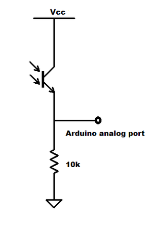
- 2. Implementation of phototransistors that allow an Arduino unit to calculate the incidence angle.
- While the original project used photoresistors, ours will use phototransistors because of their greater sensitivity.
- The phototransistor unit will be separate from the solar panel, but it will be in a fixed plane with the panel such both components experience the same angle of incidence from a sufficiently distant light source.
- The photoresistors will be in a pyramid array, exactly like the array from the hackster project.
- 3. A control algorithm for a double-step motor system based on data taken from the phototransistors and processed by the arduino.
- 4. (Stretch Goal) A scale-able design.
- The same control algorithm and photo resistor arrangement should be able to work with components of a larger physical size. This will most likely require a change in materials involved.
- The extra weight of larger frames and motors will not spoil the design
- Stretch Goal: With larger size and more weight comes more power consumption. We would need to make sure that power consumption is less than the yeild of a typical consumer panel.
Challenges
Power supply
- Can handle load bearing of panel (more of a challenge in scale).
- Consuming less power than panel is creating.
Hardware
- Implementation of stepper motors that enable dual axis rotation without unnecessary failure points
- 360 degree rotation (stepwise) without tangling of wiring.
Possible solutions
Power supply
- Drawing power from the solar panel attached would be ideal but we may try and implement a regular two prong wall plug for convenience and testing.
Safety
- Mechanical safety should not be too much of an issue given the relatively small size of our design. Safety regarding moving parts should also not be an issue as this project will be designed to move slowly in order to get accurate readings on the light sensitive phototransistors.
Budget
- Arduino Uno ($24.95)
- ITEAD Dual Step Motor Driver Shield Expansion Board Kit For Arduino ($12.00 + $4.60 shipping)
- JST Socket Connector Cables (3X$1.49 + $0.00 shipping)
- Phototransistors ($3.20 + $4.90 shipping)
- Resistors 10 kohm(10X$0.20)
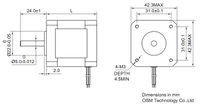
- 4 Nema 17 Stepper Motors (4X$6.99 + $10.00 shipping)
- General purpose printed circuit board ($5.99 + $4.99 shipping)
- 4.2W 12V Output USB High Efficiency Solar Panel ($12.99 + $0.00)
- Wall Adaptor Power Supply (2.1mm center positive)($5.19)
Total: $123.24


