Difference between revisions of "Holograms at Home"
| Line 107: | Line 107: | ||
== Algorithm and Actual Display Capabilities == | == Algorithm and Actual Display Capabilities == | ||
| − | + | The greatest limitation of our device is its resolution. The smallest arc that can be drawn by our device is 45 degrees. We had intended for the for a higher resolution on our display, but there were hardware limitations that prevented a higher resolution. The LED strips used in our device takes around 30 ms to write to all 96 LEDs, and because our period is around 200-300ms, this severely limited our ability to create a high-resolution display. | |
| − | |||
| − | |||
| − | |||
| − | |||
= Gantt Chart = | = Gantt Chart = | ||
Revision as of 03:01, 30 April 2017
Project Overview
Team members
- Kevin Kim
- Hyunseok Choi
- TA: William Luer
Premise
We are attempting to create a spinning LED display capable of displaying 3D objects from all directions on a cylindrical shape device. Our display can include basic shapes such as cylinders and circles. Finally, our display will be able to animate such shapes.
Objectives
- Design a mechanically robust device that will house the components including Arduino, batteries, and LEDs.
- Position each component so the device is capable of displaying basic 3D objects on a cylindrical volume.
- Develop an algorithm to control when each LED turns on and off during the display cycle.
Challenges
- Having a mechanical design that has a center of mass around the axis of rotation
- Having a mechanical design that can withstand the mechanical vibrations as the motor spins
- Mounting the device on a motor
- Mounting battery and Arduino on the spinning portion of the device
- Mounting frame unto the motor
- Building the device so the wires are not entangled while device is spinning
- Making sure wire connections do not break while the device is spinning
- Determine ideal rpm for device for visual display
- Ensuring that the display time is correct: Ensuring static display static and ensuring animations to be done at desired speed
- Designing our algorithm to optimally control the LEDs
Budget
- Arduino Mega: $0 - provided
- Arduino Redboard: $0 - provided
- 80A ESC Trackstar motor & motor controller: $0 - provided
- Electrical Tape: $0 - provided
- Electrical Wires of various color: $0 - provided
- Stepper Motor[17hs13-0404s]: $0 - provided
- Soldering Tools: $0 - provided
- 3D Printing material and 3D Printer: $0 - provided
- 2 Cell Lithium-Polyer Battery: $0 - provided
- 10 X 17 Breadboard : $0 - provided
- D batteries: $8.79 link denied by spam filter
- D Battery Connector: $4.10 link denied by spam filter
- LED strips x3: $29.95 x 3 = $89.85 [1]
- Hall Effect Sensor: $9.99 [2]
- N52 Neodymium magnets - $11.98 [3]
Total: $124.71
Design and Solutions
Constructing our device consisted of 3 major parts:
- Mechanical Design
- Circuitry and Wire Management
- Algorithm Design
Mechanical Design
Two mechanical structures were made: LED layer frame and the motor frame
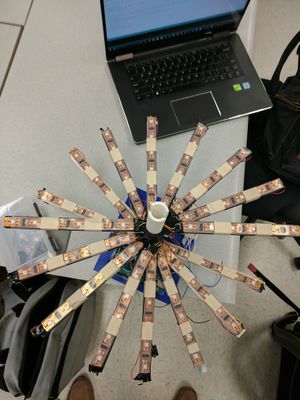
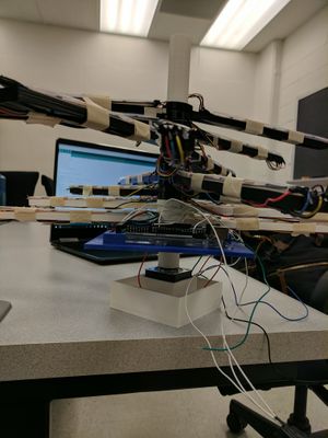
- LED layer frame (insert pictures)
The first thing we did was to create a structure that can house our LEDs, Arduino Mega, and the battery to power our Arduino.
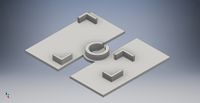
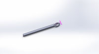
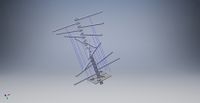
The design we came up with consisted of layers to mount LED strips on, bottom layer to house the Arduino and the battery, and a pole that can fit other parts. All designs were made using Solidworks and Autodesk Inventor. First, we designed a circular pole that can be used to fit in other parts of the frame, motor shaft, and the bearing on the bottom. Next we designed a flat, rectangular layer that can house our Arduino and the battery. Next, we modulized the design for frames that can hold LED strips. We also considered wire management issues and made the center of each circular fits hollow.
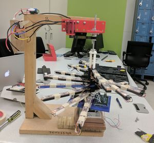
- Motor Frame (insert pics)
Design of the motor frame changed as our initial idea to use a stepper motor did not work due to lack of torque it can provide. Initially, we planned on installing a stepper motor on the bottom of the LED layer frame to spin our device. However, since the stepper motor failed to provide enough torque to spin our device, we decided to use 80A ESC Trackstar motor while keeping the stepper motor as a bearing.
We changed our design into a C-chaped structure that has the motor on the top. We initially created a wooden structure with CAD designed L-bracket on the bottom; however, the structure could not withstand the mechanical vibration caused by the motor. Through a rigorous search process, we acquired a pre-made structure with more than satisfactory mechanical robustness. We fine-tuned the frame to hold the motor and the LED layer frame.
Due to dimension and fit issues, we attached a band to the motor shaft to have it spin another thicker shaft attached to the top of the circular pole of our LED frame. We visited the machine shop to attach wooden blocks on the bottom to function as stands for the LED frame due to height issues. Next, we designed a case that can fit in the stepper motor using Solidworks. Finally, we designed and 3D printed a case that can hold our LED frame to make sure mechanical vibration hold the LED frame in place.
Note: We used 2 cell lithium-polymer battery to power our motor.
Circuitry and Wire Management
- Choosing LED strips
For convenience and wire management purposes, finding LED strips that can be controlled individually with minimum time delay was crucial. We found certain LED strips on AdaFruit that fit our purposes.
- Wiring LED strips
The difficulty in wire management came from wiring multiple LED strips. Total of 16 strips, each containing 6 LEDs, had to be wired. We wired half of the LED strips together into 1 extend strip and the same for the other. In order to manage various wires, we attached a breadboard on our LED frame. In order to help with threading wires, our design for the pole had a hollow center to thread wires through. We first taped the wires with electrical tape to secure the connections and prevent any unwanted electric connections. Realizing that the wire connections would not be secure enough, we soldered the wires to each strip. Each LED strip has 4 wires - 5V, Clock, Data, and Ground. Since we had 2 "extended" LED strips, we connected strip 1 to pins 51 and 52 and strip 2 to pins 39 and 41 on the Arduino. We connected the 5V and GND to the bread board to only have one wire be connected to 5V and GND pins on the Arduino board.
To secure the LEDs in their rightful place, since the having the correct dimensions was crucial, we taped LED strips and the wires using masking tape. Our LED strips were encases in transparent plastic bands. In order to make sure that the LED strips do not move around the bands, we stripped of each end of the bands and taped each end of the LED strips to the LED frame using transparent tape.
- Wiring Hall Effect Sensor
Wiring the hall effect sensor to the Arduino is quite simple. Hall effect sensor has 3 connections - 5V, Vin, and GND. We soldered wires to each prong and applied shrink wraps to cover the connections. We connected the 5V wire to 5V connection on the breadboard and the similar to other wires. We connected a 10kΩ resistor to go between 5V an Vin on the breadboard as required. Next, we connected the Vin to pin 2 on the Arduino. Then, we taped the hall effect sensor to the bottom of the LED frame layer holding the Arduino. We placed our neodymium magnet directly below the hall effect sensor and taped it over on the floor of the motor frame to make sure the magnet does not stick to the battery on the LED frame.
Algorithm Design
The code used to control the device consists of three parts: interpreting the information from the hall effect sensor, storing the necessary information to display images, and interpreting that information to actually display the intended image.
- The Hall Effect Sensor
The hall effect sensor basically detects when the device makes a complete revolution, and the Arduino uses this information to determine how long it takes for the device to make one revolution (the period). The period is then divided into eight equal time intervals, which other parts of the code uses.
- The Image Class
To ensure that more images could be added later on easily, we began by creating a virtual base class that all shapes that we would display (spheres, cylinders, etc.) would inherit from. All shapes basically had to answer the question, "what color lights are on at a specific angle?" The Image class answered this question by providing an 8x8x12 int array containing an integer between -1 and 255 (-1 representing the light being off, and 0-255 representing a color). Originally the Image class (and all classes that inherited it) contained an instance of the 3D array, but such a design scaled poorly, and we quickly ran into memory issues, prompting us generate the array each time we needed it, shifting the issue from memory to the processor. The Image class contains the duration (how long the image is displayed for, in number of revolutions), the color of the image (int from 0-255), and the getFrame() method, which generates the 8x8x12 array that is used to display the image.
- Reading the 8x8x12 array
The main code contains an array of Image class pointers, which represent the chain of images that the device would display, along with an instance of the 8x8x12 array containing the array of the image currently being displayed. Using the time intervals of the angles calculated from the information of the hall effect sensor, the corresponding parts of the array to set the 96 LEDs on the device to the color dictated by the array. After the duration indicated by the Image class passes, the next Image is loaded into the array, and the process repeats, until it reaches the end of the Image pointer array, at which point the first Image is displayed again.
Results
Mechanical Robustness
Mechanically, our device met our initial goals. The motor was strong, providing enough torque to spin the device at a desired rate. Our motor frame was stable enough to keep the device still despite the mechanical vibrations caused by the motor and possible angle offsets. Our LED frame, while being light, was sturdy enough to withstand the spin. Construction of our device was not too difficult nor very time consuming as we modulized various parts we designed (LED strip holding sticks). We were able to house Arduino and the battery to power the Arduino without causing any issues for the motor.
Circuitry Reliability
Soldering the wires, in fact, secured most of the connections we needed to secure. Unwanted electrical connections were minimized as a result even while spinning. LEDs were also securely taped to the LED frame that they did not move around while spinning.
Algorithm and Actual Display Capabilities
The greatest limitation of our device is its resolution. The smallest arc that can be drawn by our device is 45 degrees. We had intended for the for a higher resolution on our display, but there were hardware limitations that prevented a higher resolution. The LED strips used in our device takes around 30 ms to write to all 96 LEDs, and because our period is around 200-300ms, this severely limited our ability to create a high-resolution display.
