Difference between revisions of "EBOX"
| Line 107: | Line 107: | ||
We wanted to use a Fast Fourier Transform (FFT) in our project implementation as music is just the superposition of a bunch of different frequencies and an FFT would allow us to easily map each superposition to a numeral. | We wanted to use a Fast Fourier Transform (FFT) in our project implementation as music is just the superposition of a bunch of different frequencies and an FFT would allow us to easily map each superposition to a numeral. | ||
| − | A Fourier Transform is a transformation of a function of time into the frequencies that make it up, but a Fast Fourier Transform is an algorithm that computes the same result but in O(nlogn) time rather than O(n^2) by factorizing the discrete Fourier transform matrix into a product of mostly zeros. We | + | A Fourier Transform is a transformation of a function of time into the frequencies that make it up, but a Fast Fourier Transform is an algorithm that computes the same result but in O(nlogn) time rather than O(n^2) by factorizing the discrete Fourier transform matrix into a product of mostly zeros. We imported the FastLED library ('''reference/link library''') from the Arduino library database to translate the analog sound signals into digital signals. This decrease in complexity from a regular Discrete Fourier Transform to a Fast Fourier Transform allowed for a quick response to the audio input. Music or other forms of audio are inputted to the system through the Arduino microphone and the Arduino is programmed to take those analog signals into the FFT (Fast Fourier Transform) operations and the output is series of frequencies in the range of 0-720. |
| − | |||
| − | |||
| − | + | '''Basic implementation idea:''' | |
| − | First we have to import the library and declare all of our global variables. | + | Pseudocode: |
| − | make the array that holds the | + | |
| + | First, we have to import the library and declare all of our global variables. | ||
| + | make the array that holds the LEDs | ||
Setup{ | Setup{ | ||
| Line 128: | Line 128: | ||
} | } | ||
Show the lights | Show the lights | ||
| + | |||
add a delay so it's not constantly reading | add a delay so it's not constantly reading | ||
| + | |||
call your average function | call your average function | ||
} | } | ||
| Line 135: | Line 137: | ||
Main{ | Main{ | ||
| + | |||
Check the counter (Touch Sensor) | Check the counter (Touch Sensor) | ||
| + | |||
Reset the color mode (Options method) | Reset the color mode (Options method) | ||
| + | |||
} | } | ||
Options{ | Options{ | ||
| + | |||
if (counter value is a certain value){ | if (counter value is a certain value){ | ||
| − | put it in a | + | |
| + | put it in a certain mode | ||
| + | |||
} | } | ||
| + | |||
} | } | ||
TouchSensor{ | TouchSensor{ | ||
| + | |||
Instantiate the touch sensor and have a counter associated with it mods by the number of options you want to instantiate | Instantiate the touch sensor and have a counter associated with it mods by the number of options you want to instantiate | ||
| + | |||
} | } | ||
Average{ | Average{ | ||
| + | |||
Here you can design the running average that takes in multiple milliseconds of microphone sensor inputs and spits out one value | Here you can design the running average that takes in multiple milliseconds of microphone sensor inputs and spits out one value | ||
| + | |||
} | } | ||
White mode{ | White mode{ | ||
| − | set the lights to white (all | + | |
| + | set the lights to white (all RGB values are present in equal amounts) | ||
| + | |||
} | } | ||
Off{ | Off{ | ||
| − | set the | + | |
| + | set the RGB values to 0 | ||
| + | |||
} | } | ||
Party mode{ | Party mode{ | ||
| + | |||
Take a real-time average from the sensor value directly to decide whether or not a big shift in the music has happened (like a drop) | Take a real-time average from the sensor value directly to decide whether or not a big shift in the music has happened (like a drop) | ||
| Line 169: | Line 187: | ||
For ( each LED) | For ( each LED) | ||
| + | |||
increment each rgb value | increment each rgb value | ||
| + | |||
check the extremes for each LED color | check the extremes for each LED color | ||
| + | |||
if it goes past 255 (in our case 150) mod the value | if it goes past 255 (in our case 150) mod the value | ||
| + | |||
if it goes below 0 reset it to 0 | if it goes below 0 reset it to 0 | ||
| + | |||
else you're good | else you're good | ||
Revision as of 23:08, 8 December 2018
Project Proposal
Overview
We created an audio responsive LED lighting system integrated on a desk that can be used as a fun addition to one's home entertainment and lighting systems. The EBOX has 3 modes that the user can set with a tap of a touch sensor to customize the dynamic light patterns to fit any mood.
Group Members
Jordan Gewirtz
Chanel Lynn
Nish Chakraburtty
Tony Sancho-Spore (TA)
Dr. James Feher (Prof)
Link to Log
- https://classes.engineering.wustl.edu/ese205/core/index.php?title=EBOX_Log
- eBOX WUSTL BOX: https://wustl.app.box.com/folder/57307264614]
- Link to tutorial here
Objectives
- Use an Arduino to implement a Fast Fourier Transform(FFT)
- Integrate the FFT through the Arduino with our LED lights
- Make the LED lights respond music with a specific, non-random color scheme
- Have the Light intensity change with the decibel level of the music
- User interface
Challenges
- learn Arduino
- Soldering
- learn complex circuitry
- carpentry
- writing the code and interfacing the Arduino with the LEDs and Sound receptor
- Learn to not short our entire project
- Learn how to use transistors
- Make sure nothing blows up
- Staying under budget
Gantt Chart
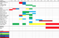
Gantt Chart
.png)
Budget
| Item | # of Units: Estimated | # of Units: Actual | Unit Price: Estimated | Unit Price: Actual | Total Price Estimated | Total Price: Actual (Including Shipping) |
| Arduino (Link) | 1 | 1 | $22.00 | $0.00 (Provided by TA) | $22.00 | $0.00 |
| Transistors (Link) | 10 | $0.06 | $0.60 | $0.00 (Provided by TA) | ||
| LED (strips - 6ft) (Link) | 1 | 1 | $21.99 | $21.99 | ||
| Arduino Microphone (Link) | 10 | 10 | $0.88 | $0.69 | $8.88 | $6.90 |
| Table (Link) | 1 | 1 | $39.99 | $39.99 | $39.99 | $43.86 |
| Capacitive Touch Sensors (Link) | - | 5 | - | $1.40 | - | $6.99 |
| Total | 14 | $48.78 |
Design And Solutions
Steps to Build the EBOX
1. Program the color patterns
2. Upload the code to the Arduino
3. Plug leads into the hardware
4. Solder external power source to lights and Arduino
5. CAD box to hold the hardware
6. Assemble table
7. Secure lights around the underside of the table
8. Plug in power source adapter to an outlet, place a speaker near the microphone, and enjoy!
Components
LED Light Strip (6ft)
Arduino Uno
Capacitive touch sensor
Sound Detection Sensor Module (Microphone)
Desk with glass or translucent top
5V Power adapter
Leads (wires)
The Software
We wanted to use a Fast Fourier Transform (FFT) in our project implementation as music is just the superposition of a bunch of different frequencies and an FFT would allow us to easily map each superposition to a numeral. A Fourier Transform is a transformation of a function of time into the frequencies that make it up, but a Fast Fourier Transform is an algorithm that computes the same result but in O(nlogn) time rather than O(n^2) by factorizing the discrete Fourier transform matrix into a product of mostly zeros. We imported the FastLED library (reference/link library) from the Arduino library database to translate the analog sound signals into digital signals. This decrease in complexity from a regular Discrete Fourier Transform to a Fast Fourier Transform allowed for a quick response to the audio input. Music or other forms of audio are inputted to the system through the Arduino microphone and the Arduino is programmed to take those analog signals into the FFT (Fast Fourier Transform) operations and the output is series of frequencies in the range of 0-720.
Basic implementation idea:
Pseudocode:
First, we have to import the library and declare all of our global variables. make the array that holds the LEDs
Setup{
instantiate your power, ground, and digital read pins
initialize your led strip in order to use the Library
For (0->numLeds){ address each LED in the Array } Show the lights
add a delay so it's not constantly reading
call your average function }
Main{
Check the counter (Touch Sensor)
Reset the color mode (Options method)
}
Options{
if (counter value is a certain value){
put it in a certain mode
}
}
TouchSensor{
Instantiate the touch sensor and have a counter associated with it mods by the number of options you want to instantiate
}
Average{
Here you can design the running average that takes in multiple milliseconds of microphone sensor inputs and spits out one value
}
White mode{
set the lights to white (all RGB values are present in equal amounts)
}
Off{
set the RGB values to 0
}
Party mode{
Take a real-time average from the sensor value directly to decide whether or not a big shift in the music has happened (like a drop)
Use that average to decide if you are in a certain song mode (if you're in the middle of a drop[large] or if you're chilling[normal])
For each song mode set up if statements that take the running average of values from the average function and if that average is in a certain range then incerement the rgb values on the leds a certain way
For ( each LED)
increment each rgb value
check the extremes for each LED color
if it goes past 255 (in our case 150) mod the value
if it goes below 0 reset it to 0
else you're good
}
Explanation of the concept:
First light up the strip to instantiate the strip. From then we want the music to be the input, so it inputs through the microphone. After we get an input, we use the FFT to convert it into value. From that frequency value, we can quantify the relative intensity of the music. However, since the microphone is picking up an obscene amount of inputs per second we should take an average every few milliseconds, hence the 'delay(10)' in the setup of the code, to get a value that we use to change the LED's color. We do this so the Arduino doesn't have to do a ridiculous amount of work by changing colors for every single input value, otherwise, the Arduino would require too much power and the circuit would fry. Based on the value obtained from the average, increment the RGB value of each LED a certain way (up to you). Make sure that the values of each RGB index for each LED has an edge case condition on incrementing the value. The max value for any RGB index is 255, so if you have a bunch of inputs all the RGB values will max out and turn to white light. To avoid this you need to make sure that the RGB values mod by 255, or a lower value if you need to draw less power so that once it hits max red, blue, or green it can reset and keep its dynamics. Now that we have music responsive lights we have to program more modes. In order to do so while allowing for user input to change the modes we employed a capacitive touch sensor, but any type of digital input sensor will work. The touch sensor is binary with it either being touched or not touched. We then instantiate a counter that increments everytime the sensor is touched. We also include in the counter definition a modular wrap around (like the wrap around in the lights) that mods by the number of modes. Now the counter will only exist as a number between 0 and (numModes -1). We then used if statements in our main method that say if the counter is a certain value then party mode, other value then desk mode, etc.
The Electronics
Background
The electronics that eBOX contains includes an Arduino Uno [1], a WS2812B LED strip [2] , a KY-038 4 pin microphone [3] , and a TTP223B digital capacitive touch sensor utilizing the self-capacitance configuration [4] [5] , all of which is soldered up to an external power source that has a standard Type A wall outlet adapter.
Design Considerations & Challenges Faced
As discussed in the Software section of this wiki, the Arduino functions as the operator of eBOX. It holds all of the code that allows eBOX to perform its functions as well as serving as the interfacing module with the other hardware components. Detailed specs with respect to the Arduino UNO can be found here. One important aspect to consider is that the Arduino UNO comes with only 2 preset 5v port, but for our setup (see figure below) 3 ports were needed. This potential hardware issue was resolved as the ports of the Arduino can be altered to give out power instead of receive information. In our case, we overrode digital port 13 to be a 5v power port instead. However, it is important to note that only devices that draw low power should be connected to the overrode port to ensure not frying the Arduino; we specifically had the touch sensor be powered by overrode port digital 13 as 2 sensors need approximately 5.5V DC and we only used one. Furthermore, an Arduino was chosen over a Raspberry Pi for simplicity sake. A rule of thumb is that an Arduino is best for repetitive tasks, like performing the same calculations over and over and updating LEDs [6].
The WS2812B LED strip is a particularly nifty piece of hardware. At 10ft long it provides ample length to satisfy any creative design one is crafting. Furthermore, not only is the strip addressable from Arduino’s fastLED Library, but each individual LED in the strip is addressable with respect to brightness and color. Additionally, the WS2812B LEDs are wired in series allowing for communication via a one-wire interface. This means that one can control each LED in the strip individually using a single Arduino digital pin. This setup also allows for the strip to be cut without damaging the LEDs that precede the cut. With respect to power, the WS2812B LED strip should be powered using 5v where each LED draws about 50mA when set at full brightness. This actually started to become an issue due to the surge protector that was part of our external power source. The surge protector would shut off the supply if the current was approaching 2.4 A. This technical issue was overcome similar to the Arduino issue via a software solution. We limited the how bright the LEDs could get by moding the RGB components by 160 instead of 255. This allowed for eBOX to run longer without running into an over consumption of power issue.
The KY-038 4 pin microphone allowed for sound detection based off the specs found here. It is crucial that the microphone has an analog out pin in order for frequency detection to be possible. If the mic only has a digital pin, only threshold sounds detection is possible based on the potentiometer setting.
The TTP223B digital capacitive touch sensor utilizing the self-capacitance configuration was ideal for functioning as a clean and simple user interface. Essentially a digital signal is sent if a human finger gets close enough to the sensor that a change in capacitance is detected. The finger functions as a dielectric as well as conductor, both contributing to an increase in capacitance. More details on how the finger functions as a dielectric and a conductor, as well as discussion on proximity vs contact can be found here. The digital signal sent to Arduino due to the change in capacitance was used to change modes from party to lamp to off, enabling a slick user interface to operate eBOX by the touch of a button.
The adapter for the external power source needed to be usable in most places. That is why we soldered an adapted with a Type A configuration. As previously discussed, the adapter had a built-in surge protector which required us to modulate our energy consumption. The adapter had inputs of 100-240V, 50/60Hz and 0.45A. It outputted 5.25V and 2400mA.
For the literal hardware set up and configuration see the diagram below

Electrical Diagram

The Housing

To hold the hardware required for the system, we 3D printed a box using OnShape, a computer-aided design software, that would hold the Arduino and other components. When designing the box, we had to consider how the Arduino would be able to access the lights, touch sensor, and a power source, so we made 3 holes in the box, one on the top and two on either side. This way, the leads from the LED strip could be fed through the top hole, the leads from the external power source could feed through a hole on the side, and the touch sensor could feed through the other hole on the side of the box. We determined that the microphone was sensitive enough that we did not need to consider placing the microphone on outside of the box, so we kept it inside the box to keep the wires out of the way. To ensure that the box would fit smoothly into the table, we excavated one corner so that it would fit into the corner of the table and the user can access the touch sensor that interfaces with the entire system.

Keeping in mind that the shell of the box and the excavated corner would take space away from the Arduino, we added about 0.5in to the dimensions of the box to ensure that everything would have space.
To secure the lights to the table, we super glued the LED strip to the inside suface of the table.
Results
Our efforts resulted in a functional led integrated table that met the parameters we set out for ourselves. We successfully designed, coded, and built and dynamically audio responsive LED light show and put it into a table. We did so at more than an affordable price point of $90 ($44 sans IKEA table expenses). Although the brightness modulation was not as extreme as we would have liked it to be, we still had the brightness modulate in response to decibels. An important decision that had to be made was the choice to modulate our individual RGB light wrap around at 150 rather than 255 (see software section of Design&Solutions for further explanation). We did so to decrease power draw and to not activate the surge protector in the external power source's adapter. Unfortunately, this resulted in a more narrow range of brightness intensities.
Shortcomings
All of the modules that we set out to use worked out and synced seamlessly. Challenges we faced included buying the right components that would give us the output we needed to conduct the Fast Fourier Transform, debugging the software, and comparing our initial objectives with the final product we felt that we reach all of our goals. Some restricted access to the workshop barred us from customizing the design of the table, although we still met our desired outcome by using a desk that had an existing transparent glass top.
Potential Next Steps
Our next steps would be to think about securing the table further by adding a waterproof seal around the glass to avoid damaging the hardware and the LED lights. This will make the product even more functional in that someone would not have to worry about their beverage affecting the components of the electrical system. Adding some additional user interfaces such as an LCD screen that tells the user what mode the system is in and making the light patterns even more dynamic through the software is in could also be next steps.
Poster
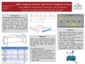
Poster

External Links
Project Proposal Presentation Powerpoint Link
References
- https://sites.wustl.edu/ese498vertigodancefloor/ (Move to the Groove Reference)
Software References
- https://github.com/kosme/arduinoFFT (Arduino FFT library)
- https:/ing /forum.arduino.cc/index.php?topic=427386.0 (Arduino FFT discussion page)
- https://www.norwegiancreations.com/2017/08/what-is-fft-and-how-can-you-implement-it-on-an-arduino/ (Arduino FFT tutorial)
- https://playground.arduino.cc/Code/Filters (Real Time Digital Signal Processing Library)
- https://www.instructables.com/id/Arduino-Audio-Input/ (Tutorial to take in audio for FFT ~40KHz)
- https://www.instructables.com/id/Arduino-Frequency-Detection/ (Tutorial to analyze in audio for FFT ~40KHz)
- https://www.instructables.com/id/Arduino-Audio-Output/ (Tutorial to output audio for FFT ~40KHz)
- https://www.youtube.com/watch?v=NQinj-tlU-M (LED coding walkthrough)
- https://www.arduino.cc/reference/en/ (Arduino Language Reference)
- https://www.youtube.com/watch?v=5oRir4dck_w (ARDUINO LED LIGHTS WORK AND ARE SOUND RECEPTIVE (with opensource code))
- http://genericnerd.blogspot.com/2009/05/arduino-mood-light-controller.html (Tutorial, LED color transitions)
- https://www.instructables.com/id/Sound-Reactive-LED-strip/ (Simple version of our project)
- https://www.youtube.com/watch?v=e1FVSpkw6q4 (Simple tutorial, make LEDs dance)
Electrical Design References
- https://www.amazon.com/DAOKI-Sensitivity-Microphone-Detection-Arduino/dp/B00XT0PH10 (purchased microphone)
- https://randomnerdtutorials.com/guide-for-microphone-sound-sensor-with-arduino/ (Guide for microphone sound sensor)
- https://www.allaboutcircuits.com/technical-articles/introduction-to-capacitive-touch-sensing/ (Understanding Capacitive Touch Sensors (Self-Capacitance Configuration))
- http://henrysbench.capnfatz.com/henrys-bench/arduino-sensors-and-input/catalex-ttp223b-arduino-capacitive-touch-sensor-tutorial/ (Tutorial Capacitive Touch Sensor Arduino)
- https://www.instructables.com/id/Wire-a-Potentiometer-as-a-Variable-Resistor/ (Potentiometer, Variable Resistor)
- https://www.instructables.com/id/How-to-use-OLED-display-arduino-module/ (Tutorial LED display)
- https://www.instructables.com/id/Sound-Reactive-LED-strip/ (Simple version of our project)
- https://www.youtube.com/watch?v=e1FVSpkw6q4 (Simple tutorial, make LEDs dance)
Physical Design References
- https://www.youtube.com/watch?v=kj-oZgmRB2w&t=73s (OnShape Tutorial)
- https://www.youtube.com/watch?v=pMWnsHpDlQE&t=18s (OnShape Tutorial)
- https://www.youtube.com/watch?v=OasbgnLOuPI (HOW TO BUILD THE TABLE AND INTEGRATE THE LEDS)
eBOX Log https://classes.engineering.wustl.edu/ese205/core/index.php?title=EBOX_Log