Difference between revisions of "Searching for Stability"
Nwschmetter (talk | contribs) |
Natalie.ng (talk | contribs) |
||
| Line 141: | Line 141: | ||
==Results== | ==Results== | ||
---- | ---- | ||
| − | + | ''Final Project:'' | |
| − | + | *The final stage of our project had unreliable motor control due to a less-than optimal control circuit and an incorrect approach to coding. However, the physical module was complete and functional. | |
| − | + | ''Comparison to Original Objectives:'' | |
| + | *The physical footprint of our the stabilizing mount was perhaps larger than expected and we were unable to complete the design for integrating the second encoder due to motor control becoming our primary focus. Despite this flaw, the most integral components of the final design align with our initial objectives. | ||
| + | *Despite the fact that we had every component we outlined in our objectives working at some point in the semester, these components never came together: when we had reliable motor control and encoder-to-motor communication, we lacked torque to correct for position, and when we torque, we lacked motor control. | ||
| + | ''Critical Decisions & Factors:'' | ||
| + | *'''Motor selection''': While we chose the best motor for our intentions, we were ignorant of the associated complications that come hand in hand with establishing control of a 3-phase brushless DC motor. | ||
| + | **Had we chosen a stepper motor, we would have had a fully functional prototype by the end of the semester. However, the lack of smooth rotation would have defeated the purpose of a gimbal. | ||
| + | **Our semester project morphed into establishing motor control as opposed to producing a functional gimbal. | ||
| + | *'''Factors:''' | ||
| + | #Humberto, our best and most critical resource on motor control, was unaware of our selection and thus the complications we were facing until there were only 3 weeks left in the semester. This left us flustered and extremely pressed for time to establish a functional solution. | ||
| + | #Our naiveté concerning our motors for the first 3/4 of the semester played a huge role in the scattered final result. | ||
| + | ##We believed that we were much further along than we really were because we thought we had reliable motor control and thought torque would be an easy fix. | ||
| + | ##Because we did not understand the underlying reason for lack of torque, we didn't realize that the motor control we had established shouldn't have been working... that is, we didn't know what we didn't know and were unable to ask question and get help sooner. | ||
| + | #When we did get help from Humberto, due to time constraints, we were given a shorthand, half-solution which we tried to implement without a complete understanding of the problem we were trying to fix. | ||
| + | ##It was not until after the demo that we were able to meet with Humberto for a substantial period of time so that he could explain to us the principles of motor control and the intricacies behind controlling our specific motor. | ||
| + | ##Without a complete understanding and with an incomplete solution (chopper circuit that delivered torque but failed to give reliable motor control), we were left to scramble in the dark trying to solve a puzzle without knowing we were missing pieces. | ||
| + | ''What We Know Now That We Should've Known Then:'' | ||
| + | *Motor control of a 3-phase brushless DC motor ''requires'' you to know the exact load you are putting on the motor, as well as the displacement of the angle of the rotor with respect to the stator. | ||
| + | *In order to find the angle of displacement we would have needed to employ either or both of the following techniques: | ||
| + | **installing an internal encoder to give angular position feedback | ||
| + | **measuring back EMF through the circuit | ||
| + | *For our intentions, three half-bridge circuits would have been much more suitable than three chopper circuits. | ||
| + | **The chopper circuit we were using is the same used by trains. Because there is no way to actually shut off the switch (will keep flowing using residual current), trains are forced to use mechanical breaks. Additionally, they need resistors as long as the train itself to dissipate the heat generated. | ||
| + | **This explains two of the issues we faced. Using an half-bridge would have eliminated the problem of over-heating our transistors and then our resistors once we added them. | ||
| + | **Additionally, the motor never saw the signal we were sending because our highest and perhaps most essential frequencies were being filtered out (low-pass filter). | ||
| + | **Half-bridge circuits resolve the heat issue and allow for precise control of the switches (transistors) | ||
| + | *With regards to code, we would have needed to implement equations when determining what signal to send out to our motor. These equations would indicate whether which phases of the motor needed to be turned on based on displacement angle and what force needed to be applied to overcome the load based on motor position (and thus angle of the load). | ||
[[Category:Projects]] | [[Category:Projects]] | ||
[[Category:Spring 2016 Projects]] | [[Category:Spring 2016 Projects]] | ||
Revision as of 19:53, 5 May 2016
Contents
Proposal
Project Description
Overview
Our project is to create a bike-mounted stabilizing platform for iPhone cinematography. We will use the readings from two magnetic encoders to control two motors responsible for stabilizing the platform. Vibration dampening pads in the mounting device itself will provide additional stability. If successful, applications of an inexpensive, compact stabilizing device could be innumerable, from handheld usage to RC and aerial filming and photography.
The mounting device of the gimbal is an original design drafted in SketchUp and produced in AutoCAD.
By the end of the semester we will be able to present iPhone footage from our device to illustrate its stabilizing capabilities.
Team Members
- Natalie Ng
- Nathan Schmetter
- Deko Ricketts (TA)
Objectives
- Program an Arduino module to receive data from magnetic rotary encoders to consistently level the iPhone while in use
- Design and construct a practical and functional mounting device for an iPhone on a bike
- Design and embed the gimbal and additional stability elements either onto or within the mounting platform itself
- Successfully stabilize the iPhone while recording a video from a moving bike
Challenges
- Perfecting the programming of the Arduino module in order to analyze the input from the two magnetic rotary encoders and communicate with the two brushless motors to re-level the iPhone
- Ensuring that input from the encoders is readable to the Arduino
- Identifying appropriate motors to carry out the stabilization of the platform
- Designing the mounting device and modifying gimbal design using 3D printer
- Finding the most effective dampening cushions considering size and weight of platform
- Compacting all elements of the design to create an unobtrusive stabilizing device
Budget
Arduino
- Parts Ordered Online
- Hardware
- 4 9V batteries ($21.99)
- 4 Screws to secure dampening pads
- 3 9V Battery Snap Connectors
- Wire
Total: $90.99
Gantt Chart


Design & Solutions
Modules
Motor Circuit
We began our journey with 3-phase induction motors knowing little else than that they were the best possible motors for generating smooth corrections such as those executed by a gimbal.
1. Direct connection: Our first motor circuit was simple, consisting of the three-phase motor and three wires that fed directly into the Arduino with our laptop as the only power source. Somehow, we managed to make this work without frying anything... Using this circuit we managed to not only get extremely reliable motor control, but also responsive communication between our encoders and our motors. The only catch was that our motors lacked torque.
                  ===>   +
                     The initial circuit.             Example of encoder-to-motor control.    Paddle rotation with initial circuit.


2. Motor Control Circuit I: After bringing our torque dilemma to Humberto's attention, he told us that there was no way our circuit should have been working, as the Arduino was not providing anywhere near the current or voltage we thought it was due to current-limiting. He suggested a completely new motor control circuit including 6 MOSFET transistors as the answer to our torque problems. Despite being warned to watch our connections as we would now be dealing with large amounts of power, we promptly fried our Arduino. Following Professor Gonzalez's roughly drawn schematic, we built the new circuit and again, managed to get a response from our motors, this time using batteries as an external power supply. For the first time, we were able to generate enough torque to spin our phone.
                                     ===>
                               Motor control circuit with motor.               First time spinning the phone.


3. Motor Control Circuit II: Though we thought we had been successful, our batteries began to die as the circuit rapidly discharged them. We realized we would need a power supply for the demo, and this is where everything became massively unreliable. Using a power supply, we would get motor control at times and minutes later the motor would be unresponsive to the same code with the same power supply settings. Additionally, a couple of our transistors were getting dangerously hot. Deko suggested that we buy 6 10 ohm, 10 watt resistors in order to get more power to our motors and to prevent our transistors from heating up. While this improvement helped with the heat issue, our reliability issues persisted.
                           ===>   +
                             Motor control circuit with              Phone rotation.              Paddle rotation.
                                       updated resistors


.gif)
How-To: MOSFET Transistor and Diode Checks
3D Design and Printing
When you compare our first design of the stabilization platform/gimbal to our last, many of the differences are blatant. However, in between these designs were many small steps and changes that each addressed a specific issue discovered after analyzing the print of the previous prototype.
- Design 1 was simply a starting point, (Figure 9). It lacked both balance and a mounting bracket for the phone case and was never printed. This iteration helped us realize that we needed a place to attach the vibration dampening pads that would smooth out the video.
- Our second design included space for the vibration dampening pads as well as a place to mount the phone. We realized that mounting the phone with such a high center of gravity would be detrimental to the stability of the platform, (Figure 10).
- Design 3 was the first model we printed, (Figure 11). We quickly realized we needed to re-think clearances because when we rotated the paddle and the phone at the same time, the phone ran into one of the upright supports. This was the first time we were able to assemble the entire prototype, including the motors and the phone. We learned that both the paddle and the phone mount were unbalanced and thus the motors could not produce enough torque to rotate them.
- The balancing process took place before printing our fourth and final prototype and is described in more depth below, (Figure 12) . After balancing, both the paddle and the phone could turn freely within the upright supports. Additionally, we added housing for the encoder that stabilized the base while allowing free rotation of the rotary shaft.

Figure 9: The first prototype lacking a mount for the phone.

Figure 10: The second prototype with a phone mount, battery storage space, and room for the Arduino.
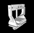
Figure 11: The third prototype displaying a significant design shift in the phone mount & central paddle.

Figure 12: The final prototype, including a counterbalance mounted on the back of the paddle.


On balancing: Balancing the phone was relatively easy. We modified the original phone mount and elongated it so that, when mounted, the phone's center of gravity lined up directly with its axis of rotation, (Figure 13, Figure 14). Balancing the paddle proved much more difficult as we had to take into account not only the center of gravity of the paddle, but also the contributions made by the center motor, the phone mount, and the phone itself. Our original paddle practically fell over and our motor had no hope of rotating it, (Figure 15). While aiming for the same center of gravity alignment achieved with the phone mount, we overcompensated on our second paddle design, which simply fell the other way, (Figure 16). Our final paddle struck a compromise and even gave us some flexibility, allowing us to load varying amounts of weight on the backside to achieve perfect balance, (Figure 17).
A simple test we used to determine if a component was balanced or not was to see if it retained its position after being rotated to any angle.
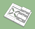
Figure 13: The original phone mount that failed to offset the phone.
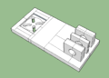
Figure 14: The second and final phone mount that accounted for the center of gravity of the phone.
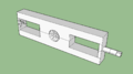
Figure 15: The original paddle that fell forwards.

Figure 16: The second paddle that fell backwards.

Figure 17: The final, balanced paddle with the motor attached along with the screw to mount counterweights.


.png)

How-To: Eliminate Internal Edges and Faces in 3D Files
Code
Our first task was writing an interrupt that would constantly poll the position of the encoder. This would enable us to know immediately if the encoder moved away from its base position and in which direction, thus allowing us to send a signal to the motor and correct for the position change. We found code online for an interrupt that converted the encoder output to integer references from 0, either positive or negative based on which way the rotary encoder turned. By roughly keeping track of a position on the outer radius of the encoder while we rotated it, we figured out that the encoder went through 78 "ticks" in each rotation.

Writing code for the motor proved to be much more complicated, though it didn't seem so at first, and we went through a number of iterations.
- Our first attempt at motor control consisted of implementing three arrays, one for each of the three phases of the motor, (Figure 19). We wrote to the three pins using a digital output signal, indicating when each phase needed to be activated (HIGH) and when it needed to be off (LOW). This code allowed us to establish smooth rotation of the motor and to control for how long the motor turned, as seen in figures 2, 3, and 5.
- Controlling the length of motor rotation involved determining how many iterations of the array were required for a single rotation. We determined that 42 position iterations was the magic number for a complete rotation.
- Because there were six positions in the array, we wrote code that took the input variable (the number of positions the motor was to rotate) and checked how many times it was divisible by 6. This corresponded to how many times the full array would be looped through. The code then checked for a remainder and instigated a second for-loop to iterate through the remaining positions (5 or less). The last position of the array was then saved in a variable so that the motor would pick up in the phase that it left off, eliminating any bouncing or jittering.
- Once we had changed our motor control circuit to the six MOSFET, six high wattage resistor circuit and were still getting unreliable motor control, Humberto told us that we needed to change our code in order to account for three variables and to generate a PWM output as opposed to a digital output. The three variables were: (1) motor frequency, (2) PWM frequency, and (3) duty cycle.
- Implementing PWM involved incredibly complex code that allows for the modification of the Arduino's internal timers. This modification then lets you set the PWM frequency of each output pin individually. We found similar code within an online PWM library and modified the Arduino UNO specific variable names to Arduino MEGA variable names so that the code would run on our microcontroller. Besides renaming variables, we also added a few more variables to account for the increase in pins from the UNO to the MEGA. This modified PWM library was then installed at the beginning of our Arduino code so that we could implement its methods.
- This code allowed us to fiddle with PWM frequency, motor frequency, and duty cycle to find the combination that would give us reliable motor control.
- Figure 20 below depicts the code used to populate the three duty cycle arrays in an effort to send three sinusoidal signals offset by 120 degrees. Each equation iterates through all 360 degrees of the unit circle and thus produces a sine wave that peaks at 255 (the maximum of a PWM duty cycle) and has a minimum of 0 (the minimum of a PWM duty cycle). The variable that is changed in between each position of the array is changed by pi/180 which gives the value of a 1 degree rotation in radians. This variable gets reset if it gets above 359*pi/360 indicating that you have traveled all the way around the unit circle.
- While we were able to establish eratic control of our motors using the modified code, we continued to struggle and Humberto later told us that our three-phase motors needed a signal that looked sinusoidal but that was not actually so.

Figure 19: The first set of arrays implemented for motor control.

Figure 20: The second set of arrays implemented for motor control & how they were populated.

How-To: Write an Arduino Interrupt
Results
Final Project:
- The final stage of our project had unreliable motor control due to a less-than optimal control circuit and an incorrect approach to coding. However, the physical module was complete and functional.
Comparison to Original Objectives:
- The physical footprint of our the stabilizing mount was perhaps larger than expected and we were unable to complete the design for integrating the second encoder due to motor control becoming our primary focus. Despite this flaw, the most integral components of the final design align with our initial objectives.
- Despite the fact that we had every component we outlined in our objectives working at some point in the semester, these components never came together: when we had reliable motor control and encoder-to-motor communication, we lacked torque to correct for position, and when we torque, we lacked motor control.
Critical Decisions & Factors:
- Motor selection: While we chose the best motor for our intentions, we were ignorant of the associated complications that come hand in hand with establishing control of a 3-phase brushless DC motor.
- Had we chosen a stepper motor, we would have had a fully functional prototype by the end of the semester. However, the lack of smooth rotation would have defeated the purpose of a gimbal.
- Our semester project morphed into establishing motor control as opposed to producing a functional gimbal.
- Factors:
- Humberto, our best and most critical resource on motor control, was unaware of our selection and thus the complications we were facing until there were only 3 weeks left in the semester. This left us flustered and extremely pressed for time to establish a functional solution.
- Our naiveté concerning our motors for the first 3/4 of the semester played a huge role in the scattered final result.
- We believed that we were much further along than we really were because we thought we had reliable motor control and thought torque would be an easy fix.
- Because we did not understand the underlying reason for lack of torque, we didn't realize that the motor control we had established shouldn't have been working... that is, we didn't know what we didn't know and were unable to ask question and get help sooner.
- When we did get help from Humberto, due to time constraints, we were given a shorthand, half-solution which we tried to implement without a complete understanding of the problem we were trying to fix.
- It was not until after the demo that we were able to meet with Humberto for a substantial period of time so that he could explain to us the principles of motor control and the intricacies behind controlling our specific motor.
- Without a complete understanding and with an incomplete solution (chopper circuit that delivered torque but failed to give reliable motor control), we were left to scramble in the dark trying to solve a puzzle without knowing we were missing pieces.
What We Know Now That We Should've Known Then:
- Motor control of a 3-phase brushless DC motor requires you to know the exact load you are putting on the motor, as well as the displacement of the angle of the rotor with respect to the stator.
- In order to find the angle of displacement we would have needed to employ either or both of the following techniques:
- installing an internal encoder to give angular position feedback
- measuring back EMF through the circuit
- For our intentions, three half-bridge circuits would have been much more suitable than three chopper circuits.
- The chopper circuit we were using is the same used by trains. Because there is no way to actually shut off the switch (will keep flowing using residual current), trains are forced to use mechanical breaks. Additionally, they need resistors as long as the train itself to dissipate the heat generated.
- This explains two of the issues we faced. Using an half-bridge would have eliminated the problem of over-heating our transistors and then our resistors once we added them.
- Additionally, the motor never saw the signal we were sending because our highest and perhaps most essential frequencies were being filtered out (low-pass filter).
- Half-bridge circuits resolve the heat issue and allow for precise control of the switches (transistors)
- With regards to code, we would have needed to implement equations when determining what signal to send out to our motor. These equations would indicate whether which phases of the motor needed to be turned on based on displacement angle and what force needed to be applied to overcome the load based on motor position (and thus angle of the load).