Difference between revisions of "Cheers! Weekly Log"
Jessieshi97 (talk | contribs) |
Jessieshi97 (talk | contribs) |
||
| Line 16: | Line 16: | ||
[[File:HX1.jpeg|thumb|Figure 1|400px]] | [[File:HX1.jpeg|thumb|Figure 1|400px]] | ||
# Proposal | # Proposal | ||
| − | * Changed the stepper motor to servo motor to avoid from getting hot at zero speed. | + | #* Changed the stepper motor to servo motor to avoid from getting hot at zero speed. |
| − | * Added the 2 double pulley system to cut the weight of the bottle (with soda) to 1/4 of its original weight as sensed by the motor. | + | #* Added the 2 double pulley system to cut the weight of the bottle (with soda) to 1/4 of its original weight as sensed by the motor. |
| − | * Added the wooden cover idea to the proposal to separate the mechanical system from the electrical system. The mechanical system will be built on top of the electrical system and the wires to connect to the weight sensor is through the base (will not be out in air). | + | #* Added the wooden cover idea to the proposal to separate the mechanical system from the electrical system. The mechanical system will be built on top of the electrical system and the wires to connect to the weight sensor is through the base (will not be out in air). |
| − | * Researched various ways of supplying power to the servo motor, whether is it through the Arduino board portal, using two separate power supplies or connecting the Arduino board and the two motor in parallel or series, etc. We decided to use a single power supply and connecting the two motors and Arduino board all parallel to each other. The power supply would be 6V 3A wall power adaptor. The two motors can operate at the voltage of 4.8V to 6V(correspond to maximum stall torque) and the Arduino board can operate at a minimum of 6V. As we will not need the Arduino board to supply a lot of power (push button and weight sensor), we thought it should be fine. | + | #* Researched various ways of supplying power to the servo motor, whether is it through the Arduino board portal, using two separate power supplies or connecting the Arduino board and the two motor in parallel or series, etc. We decided to use a single power supply and connecting the two motors and Arduino board all parallel to each other. The power supply would be 6V 3A wall power adaptor. The two motors can operate at the voltage of 4.8V to 6V(correspond to maximum stall torque) and the Arduino board can operate at a minimum of 6V. As we will not need the Arduino board to supply a lot of power (push button and weight sensor), we thought it should be fine. |
# Mechanical System | # Mechanical System | ||
| − | * Started building the model the part 1 of the base and learned to use the Ultimaker 2 Extended machine with Natalie and Nathan over the weekend. | + | #* Started building the model the part 1 of the base and learned to use the Ultimaker 2 Extended machine with Natalie and Nathan over the weekend. |
| + | #* Printed the first model of base 1. | ||
<gallery mode=packed heights=200px style="text-align:left"> | <gallery mode=packed heights=200px style="text-align:left"> | ||
File:Cpic1.PNG| Base 1 | File:Cpic1.PNG| Base 1 | ||
Revision as of 20:52, 3 March 2017
Contents
Week 1 (1/23 - 1/29)
Formulate group and brainstorm about project ideas. We decided to replicate a beer pouring machine on youtube.
Week 2 (1/30 - 2/5)

We met with Natalie (TA) to help us straighten the project objective, determine several potential challenges and write out the project proposal. We researched about the specific mechanism to control tilt angles as it was not clearly shown in the video It was decided that we use two 90 degrees lever, each for soda bottle and glassware, tied with a fishing line connected to a spool on a step motor to control the tilt angle (Figure 1). The start for the system is controlled by a push button and the stop pouring signal should be decided by laser detection. Arduino was found to be useful in the process in controlling this process. For a potentially successful project, the budget was determined after objective and challenges were identified.
Week 3 (2/6-2/12)

We compared the pros and cons of various available sensors (distance sensor, color sensor, laser sensor, liquid level sensor and weight sensors) and decided to change our laser sensor to weight sensor. Other sensors all have high chances of electric shock as it is very hard to cover the sensor to prevent liquid damage. Weight sensor could be hidden in the base holder of the glassware and the wires are sent to the Arduino board inside the support stands. In addition, we decided to put a wooden cover on the Arduino board and stepper motor. The fishing line will be sent out from the cover through a little hole and connect to the lever using four pulleys. We together altered the objective in the project proposal to make the mechanical models and its tilting mechanism more robust.
Haixiang finished the tutorial on Introduction to Solidworks and Tutorial 1. Jessie started drawing pictures for the mechanical design of the system and editing the project proposal page. We realized that 3D printing could only print a maximum length of 8 inches so we decided to print three supportive stands on each side to make a strong base, and each stand will be made out of 2 pieces of 3D printings.
Week 4 (2/13-2/19)

- Proposal
- Changed the stepper motor to servo motor to avoid from getting hot at zero speed.
- Added the 2 double pulley system to cut the weight of the bottle (with soda) to 1/4 of its original weight as sensed by the motor.
- Added the wooden cover idea to the proposal to separate the mechanical system from the electrical system. The mechanical system will be built on top of the electrical system and the wires to connect to the weight sensor is through the base (will not be out in air).
- Researched various ways of supplying power to the servo motor, whether is it through the Arduino board portal, using two separate power supplies or connecting the Arduino board and the two motor in parallel or series, etc. We decided to use a single power supply and connecting the two motors and Arduino board all parallel to each other. The power supply would be 6V 3A wall power adaptor. The two motors can operate at the voltage of 4.8V to 6V(correspond to maximum stall torque) and the Arduino board can operate at a minimum of 6V. As we will not need the Arduino board to supply a lot of power (push button and weight sensor), we thought it should be fine.
- Mechanical System
- Started building the model the part 1 of the base and learned to use the Ultimaker 2 Extended machine with Natalie and Nathan over the weekend.
- Printed the first model of base 1.
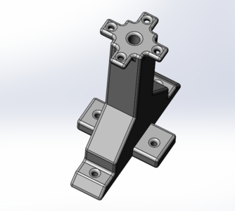
Base 1
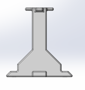
Base 1


Week 5 (2/20-2/26)

Proposal:
- updated the wooden base system so that our electronics will be kept above the height of the mechanical system to prevent electric shock
Mechanical System:
- Adjusted the part 1 base so that the attachment part to part 2 of the base will not interfere with the swing.
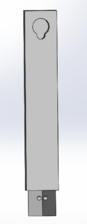
- Calculated exact parameters needed and designed part 2 of the base, the horizontal rotating axis.
- Start printing out the parts
- Had a rough 3D model for the bottle holder and the lever arm and how it will be attached to the horizontal arm.
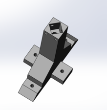
Base 1 edited
Base 2 (will be put on top of base 1)
Horizontal Rotation Axis


