Difference between revisions of "Finding Fëanor"
m (Protected "Finding Fëanor" ([Edit=Allow only administrators] (indefinite) [Move=Allow only administrators] (indefinite))) |
|||
| (23 intermediate revisions by one other user not shown) | |||
| Line 62: | Line 62: | ||
=== Mechanical Design === | === Mechanical Design === | ||
| + | [[File: Frame_Model.PNG|100px|thumb|right]] | ||
| + | [[File: Panel Mount Model.PNG|100px|thumb|right]] | ||
| + | [[File: Pyramid_Model.PNG|100px|thumb|right]] | ||
After preliminary research, we came across a project on Hackster (mentioned in overview) which gave us a base point for the pivoting U-frame design. It quickly became evident that 3D printing would allow us to take significant departures from the original design. | After preliminary research, we came across a project on Hackster (mentioned in overview) which gave us a base point for the pivoting U-frame design. It quickly became evident that 3D printing would allow us to take significant departures from the original design. | ||
| Line 69: | Line 72: | ||
Another improvement we made to the original project had to do with the mounting of the bottom stepper motor. Instead of attaching the pin to the frame, we found we could get more stability by using the screw holes already in the motor. The pin of the motor does not rotate. Instead, it is held stationary by a heat shrink inside a block of wood while the rest of the motor is free to rotate within the constraint of the power cord. | Another improvement we made to the original project had to do with the mounting of the bottom stepper motor. Instead of attaching the pin to the frame, we found we could get more stability by using the screw holes already in the motor. The pin of the motor does not rotate. Instead, it is held stationary by a heat shrink inside a block of wood while the rest of the motor is free to rotate within the constraint of the power cord. | ||
| + | |||
| + | [[File:TransistorCircuit.png|150px|thumb|left|Circuit used to read voltages from photo-transistors]] | ||
=== Circuitry and Wire Management === | === Circuitry and Wire Management === | ||
Our light sensing device is fairly simple and is made out of four basic photo-transistor circuits, each composed of a phototransistor and a 1MΩ resistor. The apparatus to put these photo-transistors to good use is a 3D printed square pyramid with a 0.5cm diameter hole in the middle of each of the four triangular faces. The holes allow the phototransistors to be glued in place and still have their wires be usable in the interior of the pyramid. All the positive voltage leads were soldered to a wire that will provide power to all four circuits directly from the Arduino. The remaining leads of each photo-transistor are soldered to a 4-set ribbon wire as to consolidate all four of these loose wires. From the pyramid apparatus, this ribbon wire is fed under the solar panel and is soldered onto the circuit board mounted there. Soldered to the circuit board are all four 1MΩ resistors, 3 jumpers to connect the resistors, a wire leading from these jacks to ground, and an additional ribbon wire to connect the photo-transistor outputs to Arduino pins A0, A1, A2, and A3. | Our light sensing device is fairly simple and is made out of four basic photo-transistor circuits, each composed of a phototransistor and a 1MΩ resistor. The apparatus to put these photo-transistors to good use is a 3D printed square pyramid with a 0.5cm diameter hole in the middle of each of the four triangular faces. The holes allow the phototransistors to be glued in place and still have their wires be usable in the interior of the pyramid. All the positive voltage leads were soldered to a wire that will provide power to all four circuits directly from the Arduino. The remaining leads of each photo-transistor are soldered to a 4-set ribbon wire as to consolidate all four of these loose wires. From the pyramid apparatus, this ribbon wire is fed under the solar panel and is soldered onto the circuit board mounted there. Soldered to the circuit board are all four 1MΩ resistors, 3 jumpers to connect the resistors, a wire leading from these jacks to ground, and an additional ribbon wire to connect the photo-transistor outputs to Arduino pins A0, A1, A2, and A3. | ||
| − | |||
Each stepper motor has a 4-set of ribbon wire soldered to its four protruding output wires and fed directly into the motor shield. The 3D printed frame has rectangular holes on all its sides making it easier to feed the wires directly to their respective pins on the Arduino and to ensure these additional wires do not interfere with the rotation of the solar panel. | Each stepper motor has a 4-set of ribbon wire soldered to its four protruding output wires and fed directly into the motor shield. The 3D printed frame has rectangular holes on all its sides making it easier to feed the wires directly to their respective pins on the Arduino and to ensure these additional wires do not interfere with the rotation of the solar panel. | ||
| Line 95: | Line 99: | ||
== Results and Next Steps == | == Results and Next Steps == | ||
| − | |||
| − | |||
| + | Our group is satisfied with the outcome of the project. We can accurately track the movement of a light source within a reasonable tolerance which satisfies our goal of improving the output of a solar panel. However, there were a few bugs and missed opportunities worth discussing: | ||
| + | [[File: Trim.1B994E63-F578-41B7-956C-41E0D6BDECA0.MOV|thumb|portrait|right|600px|Preliminary testing. Here, the apparatus misses steps about 16 seconds into the video. This problem was solved by slowing the rotation speed of the bottom stepper.]] | ||
* Mechanical vibrations turned out to be more of an issue than we imagined they would. While the system still worked more or less how we thought it would, the twitchy nature of the motors made the project seem unrefined. One way to address this would be to increase the speed of rotation. While testing, we found that the lower the motor's rpm, the more vibrations occurred. Unfortunately, at higher rpm we tended to lose steps in the algorithm's step counter. More work is needed, but we believe the problem lies in either the algorithm being used or the speed at which the system rotates. | * Mechanical vibrations turned out to be more of an issue than we imagined they would. While the system still worked more or less how we thought it would, the twitchy nature of the motors made the project seem unrefined. One way to address this would be to increase the speed of rotation. While testing, we found that the lower the motor's rpm, the more vibrations occurred. Unfortunately, at higher rpm we tended to lose steps in the algorithm's step counter. More work is needed, but we believe the problem lies in either the algorithm being used or the speed at which the system rotates. | ||
* As far as the algorithm is concerned, everything works exactly as we envisioned. At the outset of our project, Dr. Gonzalez suggested we use the output of the solar panel as a secondary virtual sensor to aid in fine adjustments of the angle. In a sense, the pyramid of phototransistors would act as a first watch to initialize an optimal angle. Once that angle was achieved, the solar panel would pivot a small number of steps in the four available directions while the output at each adjusted angle was measured. This would, in effect, give us a system with nested tolerances. While this would undoubtedly give us a more accurate system, we ran out of time to implement it because of the late arrival of parts. | * As far as the algorithm is concerned, everything works exactly as we envisioned. At the outset of our project, Dr. Gonzalez suggested we use the output of the solar panel as a secondary virtual sensor to aid in fine adjustments of the angle. In a sense, the pyramid of phototransistors would act as a first watch to initialize an optimal angle. Once that angle was achieved, the solar panel would pivot a small number of steps in the four available directions while the output at each adjusted angle was measured. This would, in effect, give us a system with nested tolerances. While this would undoubtedly give us a more accurate system, we ran out of time to implement it because of the late arrival of parts. | ||
| − | * The wiring is a bit unprofessional as we heavily prioritized getting the system working before we worried about cosmetics. Implementing more compact wiring solutions would be a top priority for a Finding | + | * The wiring is a bit unprofessional as we heavily prioritized getting the system working before we worried about cosmetics. Implementing more compact wiring solutions would be a top priority for a Finding Fëanor redux. |
| + | |||
| − | === Future | + | === Future Considerations === |
Future projects could take advantage of the progress that we made and continue to refine both the algorithm and the mechanical design. Additionally, groups could work on scaling up the technology, working to power the setup with the solar panel itself, or using different sensors (e.g. motion sensing) on the same setup to create a movement tracking device for a camera. | Future projects could take advantage of the progress that we made and continue to refine both the algorithm and the mechanical design. Additionally, groups could work on scaling up the technology, working to power the setup with the solar panel itself, or using different sensors (e.g. motion sensing) on the same setup to create a movement tracking device for a camera. | ||
Latest revision as of 05:22, 15 December 2016
Contents
Project Overview
The primary drawback of solar panels as a commercially viable energy harvesting application is the high cost per energy harvested. Currently, the best consumer solar modules are able to achieve an efficiency of 24%, meaning that about 24% of incident solar radiation is converted to usable electrical energy. That figure is astounding if one examines previous maximum efficiency in consumer models throughout the technology's development.
This success aside, our group believes that the core issue of high cost per energy harvested is still not being addressed in a practical way, which is the motivation behind our project, Finding Fëanor. A portion of the inefficient energy conversion stems from the changing angle of incident sunlight with the respect to a given solar panel. The closer to 90˚ between the face of the solar panel and the path of sunlight, the more optimum the collection is. The problem with current products on the market is that most are static panels that cannot change in response to the changing angle, driving their already low power output even lower.
Our solution is to build an Arduino-controlled system that allows for two axes of rotation. This would allow a panel in almost any setting or application to be dynamically adjusted to the changing incident angle of light. While doing preliminary research, we came across a project almost identical in motivation and scope. We decided that improving upon this project would give allow us to experience a design project more holistically than if we had to start from scratch. This also means we will be attempting to optimize some aspects of the old design. These optimizations are covered in the objective portion of the proposal.
Team Members
- John Fordice
- Zach Pewitt
- Sam Donaldson
- Will Luer (TA)
Objectives
A successful project will require:
- 1. A frame that allows for dual axis rotation.
- A base which will most likely be made from a block of wood.
- A 3D-printed U-frame to house the panel itself.
- 2. Implementation of phototransistors that allow an Arduino unit to calculate the incidence angle.
- While the original project used photoresistors, ours will use phototransistors because of their greater sensitivity.
- The phototransistor unit will be separate from the solar panel, but it will be in a fixed plane with the panel such both components experience the same angle of incidence from a sufficiently distant light source.
- The photoresistors will be in a pyramid array, exactly like the array from the hackster project.
- 3. A control algorithm for a motor system based on data taken from the phototransistors and processed by the arduino.
- 4. (Stretch Goal) A scale-able design.
- The same control algorithm and photo resistor arrangement should be able to work with components of a larger physical size. This will most likely require a change in materials involved.
- The extra weight of larger frames and motors will not spoil the design
- Stretch Goal: With larger size and more weight comes more power consumption. We would need to make sure that power consumption is less than the yeild of a typical consumer panel.
Challenges
Power supply
- Can handle load bearing of panel (more of a challenge at large scale).
Hardware
- Implementation of stepper motors that enable dual axis rotation without unnecessary failure points
- 360 degree rotation (stepwise) without tangling of wiring
- Keeping control systems stable during rotation
Power supply
- Drawing power from the solar panel attached would be ideal but we may try and implement a regular two prong wall plug for convenience and testing.
Safety
- Mechanical safety should not be too much of an issue given the relatively small size of our design. Safety regarding moving parts should also not be an issue as this project will be designed to move slowly in order to get accurate readings on the light sensitive phototransistors.
Budget
- Arduino Uno ($24.95)
- ITEAD Dual Step Motor Driver Shield Expansion Board Kit For Arduino ($12.00 + $4.60 shipping)
- JST Socket Connector Cables (3X$1.49 + $0.00 shipping)
- Phototransistors ($3.20 + $4.90 shipping)
- Resistors 10 kohm(10X$0.20)
- 4 Nema 17 Stepper Motors (4X$6.99 + $10.00 shipping)
- General purpose printed circuit board ($5.99 + $4.99 shipping)
- 4.2W 12V Output USB High Efficiency Solar Panel ($12.99 + $0.00)
- Wall Adaptor Power Supply (2.1mm center positive)($5.19)
Total: $123.24
Design Solutions
Mechanical Design
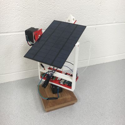
After preliminary research, we came across a project on Hackster (mentioned in overview) which gave us a base point for the pivoting U-frame design. It quickly became evident that 3D printing would allow us to take significant departures from the original design.
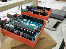
We were able to mount the Arduino and motor shield on the system itself which allowed for a more compact form factor. This allowed us to eliminate most of the rotational constraints. We didn’t want to risk a battery-powered set-up for the demo for fear of running low on charge so the constraint of a power cord to the system remained.
Another improvement we made to the original project had to do with the mounting of the bottom stepper motor. Instead of attaching the pin to the frame, we found we could get more stability by using the screw holes already in the motor. The pin of the motor does not rotate. Instead, it is held stationary by a heat shrink inside a block of wood while the rest of the motor is free to rotate within the constraint of the power cord.
Circuitry and Wire Management
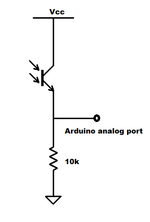
Our light sensing device is fairly simple and is made out of four basic photo-transistor circuits, each composed of a phototransistor and a 1MΩ resistor. The apparatus to put these photo-transistors to good use is a 3D printed square pyramid with a 0.5cm diameter hole in the middle of each of the four triangular faces. The holes allow the phototransistors to be glued in place and still have their wires be usable in the interior of the pyramid. All the positive voltage leads were soldered to a wire that will provide power to all four circuits directly from the Arduino. The remaining leads of each photo-transistor are soldered to a 4-set ribbon wire as to consolidate all four of these loose wires. From the pyramid apparatus, this ribbon wire is fed under the solar panel and is soldered onto the circuit board mounted there. Soldered to the circuit board are all four 1MΩ resistors, 3 jumpers to connect the resistors, a wire leading from these jacks to ground, and an additional ribbon wire to connect the photo-transistor outputs to Arduino pins A0, A1, A2, and A3.
Each stepper motor has a 4-set of ribbon wire soldered to its four protruding output wires and fed directly into the motor shield. The 3D printed frame has rectangular holes on all its sides making it easier to feed the wires directly to their respective pins on the Arduino and to ensure these additional wires do not interfere with the rotation of the solar panel.
The Arduino to USB power cable is the only wire that is not contained within the moving parts of the solar panel mount. If the base is round then the cord will have no problem winding itself around until the rotation of the solar panel mount exceeds the length of the cable. If the base is a polygon (like ours) the cable can virtually do the same thing but take greater care to make sure it does not get suck on a corner.
- Note: All solder joints are wrapped in electrical tape to ensure there is no electrical interference from neighboring wires.
- Note: Make sure wires going from circuit board to the Arduino are long enough so they do not interfere with the panel’s rotation.
Algorithm Design
Though we had an idea for the general structure of the algorithm, the design of the algorithm did not begin until after the stepper motors and the motor shield arrived.
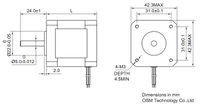
The motors used (NEMA 17) were designed to only draw 350 mA and, as such, could be controlled by an arduino through a stepper shield. A native arduino library saved us the hassle of authoring functions to control the motors ourselves. This library, conveniently named “Stepper.h”, included functions to define specific stepper objects, specify the rotation speed, and individually step each of the motors. We wrote a simple arduino sketch to familiarize ourselves with the library and its use. With the motor control fully understood, the next step was to include and read the phototransistors.
After the electrical circuit was completed, it was a simple step to read in the voltages from the phototransistors. A high resistance in the biasing circuit allows for a greater range of output voltages based on the amount of incoming light. The analogRead() command allows the arduino to read the values from each transistor. With the motor control understood and the phototransistor voltages available, the final step was to actually construct the algorithm.
The algorithm used in this setup is a basic greedy search algorithm. First, it reads in the voltage data from the phototransistors and assigns each to its own variable. Next, it compares the left and right phototransistors and assigns this difference to another variable. The same process is followed with the top and bottom phototransistors. These two values are then compared to a predefined tolerance and if they are outside of the absolute value of this range the steppers are adjusted as to minimize this difference. If the left phototransistor was higher than the right, for example, the horizontal stepper motor would be incremented to turn the pyramid toward the light source and work to minimize this difference. Every time the motors are incremented or decremented, a counter is updated to match the number of steps taken. If this counter reaches the amount of steps that corresponds to a half rotation in the horizontal direction or a quarter rotation in the vertical direction, the motor will not increment any further. Each iteration of the algorithm can only step the motor once, but because it is run continuously it gives the illusion of smooth movement.
After the setup was completed and the algorithm was uploaded to the arduino, we tuned some of the specific parameters. First, we tested several tolerance limits and actually used a separate tolerance for the vertical movement and horizontal movement. Additionally, we looked at using several different motor speeds. A speed of 200 rpm was used for the vertical axis, while a slower speed of 125 rpm was used for the horizontal axis to minimize the loss of steps.
Results and Next Steps
Our group is satisfied with the outcome of the project. We can accurately track the movement of a light source within a reasonable tolerance which satisfies our goal of improving the output of a solar panel. However, there were a few bugs and missed opportunities worth discussing:
- Mechanical vibrations turned out to be more of an issue than we imagined they would. While the system still worked more or less how we thought it would, the twitchy nature of the motors made the project seem unrefined. One way to address this would be to increase the speed of rotation. While testing, we found that the lower the motor's rpm, the more vibrations occurred. Unfortunately, at higher rpm we tended to lose steps in the algorithm's step counter. More work is needed, but we believe the problem lies in either the algorithm being used or the speed at which the system rotates.
- As far as the algorithm is concerned, everything works exactly as we envisioned. At the outset of our project, Dr. Gonzalez suggested we use the output of the solar panel as a secondary virtual sensor to aid in fine adjustments of the angle. In a sense, the pyramid of phototransistors would act as a first watch to initialize an optimal angle. Once that angle was achieved, the solar panel would pivot a small number of steps in the four available directions while the output at each adjusted angle was measured. This would, in effect, give us a system with nested tolerances. While this would undoubtedly give us a more accurate system, we ran out of time to implement it because of the late arrival of parts.
- The wiring is a bit unprofessional as we heavily prioritized getting the system working before we worried about cosmetics. Implementing more compact wiring solutions would be a top priority for a Finding Fëanor redux.
Future Considerations
Future projects could take advantage of the progress that we made and continue to refine both the algorithm and the mechanical design. Additionally, groups could work on scaling up the technology, working to power the setup with the solar panel itself, or using different sensors (e.g. motion sensing) on the same setup to create a movement tracking device for a camera.


