Difference between revisions of "Smarter Blinds"
Lkaniewski (talk | contribs) |
m (Protected "Smarter Blinds" ([Edit=Allow only administrators] (indefinite) [Move=Allow only administrators] (indefinite))) |
||
| (39 intermediate revisions by 2 users not shown) | |||
| Line 65: | Line 65: | ||
*Arduino Feather ($29.95) | *Arduino Feather ($29.95) | ||
Current Amount Spent: $49.44 + $7.15 = $56.59 | Current Amount Spent: $49.44 + $7.15 = $56.59 | ||
| − | |||
=== Gantt Chart === | === Gantt Chart === | ||
| + | [[File:SmarterBlindsGanttChart.png|thumb|Gantt Chart]] | ||
[https://docs.google.com/spreadsheets/d/10uzT7YQ7MJU3zTquifuFkcKUptFDYlntzzncpx78SI4/edit?usp=sharing Gantt Chart ] | [https://docs.google.com/spreadsheets/d/10uzT7YQ7MJU3zTquifuFkcKUptFDYlntzzncpx78SI4/edit?usp=sharing Gantt Chart ] | ||
| − | |||
== Design and Solutions == | == Design and Solutions == | ||
| Line 75: | Line 74: | ||
=== Mechanics === | === Mechanics === | ||
==== Construction of Circuit ==== | ==== Construction of Circuit ==== | ||
| − | [[File: | + | [[File:RealSchematic.png | thumb | Schematic of parts connected to Adafruit Feather 32u4]] |
[[File:breadboard.png | thumb | Breadboard view of parts connected to Adafruit Feather 32u4]] | [[File:breadboard.png | thumb | Breadboard view of parts connected to Adafruit Feather 32u4]] | ||
Initially, the temperature sensor, photoresistor, hall effect sensor, and motor were set up individually on the breadboard and tested with the Arduino. After troubleshooting individual threads of code and making sure each component functioned properly in the circuit, the components were set up together on the breadboard. The three legs of the temperature sensor are connected to positive, A0, and ground, respectively. For the hall effect sensor, the left leg of the hall effect sensor connects to a 10k resistor and then to positive, the middle leg connects to the right leg of the temperature sensor and then to ground, and the right leg connects to the other end of the 10k resistor and then to pin 12. One leg of the photoresistor connects to positive, and the other leg connects to one end of another 10k resistor and then to A1. The other end of the most recently mentioned 10k resistor connects directly to negative. For the motor, the gray wire connects to positive, and the brown wire connects to negative. The positive end of the circuit is then connected to 5V, which is labeled as USB on the Feather, and the negative end is connected to ground. This explanation can be clearly seen in the perfboard sketch pictured below. After determining all of these connections, everything was soldered onto the perfboard, along with pins to easily connect to the headers of the feather with jumper wires. | Initially, the temperature sensor, photoresistor, hall effect sensor, and motor were set up individually on the breadboard and tested with the Arduino. After troubleshooting individual threads of code and making sure each component functioned properly in the circuit, the components were set up together on the breadboard. The three legs of the temperature sensor are connected to positive, A0, and ground, respectively. For the hall effect sensor, the left leg of the hall effect sensor connects to a 10k resistor and then to positive, the middle leg connects to the right leg of the temperature sensor and then to ground, and the right leg connects to the other end of the 10k resistor and then to pin 12. One leg of the photoresistor connects to positive, and the other leg connects to one end of another 10k resistor and then to A1. The other end of the most recently mentioned 10k resistor connects directly to negative. For the motor, the gray wire connects to positive, and the brown wire connects to negative. The positive end of the circuit is then connected to 5V, which is labeled as USB on the Feather, and the negative end is connected to ground. This explanation can be clearly seen in the perfboard sketch pictured below. After determining all of these connections, everything was soldered onto the perfboard, along with pins to easily connect to the headers of the feather with jumper wires. | ||
| Line 84: | Line 83: | ||
==== 3D Printing ==== | ==== 3D Printing ==== | ||
[[File:Enclosure.png | thumb | Enclosure for electronics created via OnShape]] | [[File:Enclosure.png | thumb | Enclosure for electronics created via OnShape]] | ||
| − | OnShape software was used to design the connector between the blinds and the stepper motor as well as the enclosure for the Feather, perfboard, and motor. The enclosure is designed to easily clamp on and off of the top of any blinds without any messy installation. A circular extrusion from the part of the enclosure that holds the motor and motor driver allows for a connector to be attached between the rotating hook of the blinds and the motor. | + | [[File:connectortop.png | thumb | Connector between stepper motor and blinds created via OnShape]] |
| + | OnShape<ref>OnShape 3D Printing https://www.onshape.com/</ref> software was used to design the connector between the blinds and the stepper motor as well as the enclosure for the Feather, perfboard, and motor. The enclosure is designed to easily clamp on and off of the top of any blinds without any messy installation. A circular extrusion from the part of the enclosure that holds the motor and motor driver allows for a connector to be attached between the rotating hook of the blinds and the motor. | ||
==== Mounting Blinds ==== | ==== Mounting Blinds ==== | ||
| Line 91: | Line 91: | ||
=== Programming === | === Programming === | ||
==== Detecting Temperature of Room ==== | ==== Detecting Temperature of Room ==== | ||
| − | [[File:tempsensor.png|thumb|Temperature | + | [[File:tempsensor.png|thumb|Code for Detecting Temperature of Room]] |
| − | An LM35DX temperature sensor measures the temperature of the room in which the blinds are located. The voltage is detected from the temperature pin, and this value is converted into degrees Celsius and then into degrees Fahrenheit, as seen in lines 7 through 9 of the code. | + | An LM35DX temperature sensor<ref> Temperature Sensor https://www.arduino.cc/en/uploads/Main/TemperatureSensor.pdf</ref> measures the temperature of the room in which the blinds are located. The voltage is detected from the temperature pin, and this value is converted into degrees Celsius and then into degrees Fahrenheit, as seen in lines 7 through 9 of the code. |
==== Detecting Luminosity of Room ==== | ==== Detecting Luminosity of Room ==== | ||
| − | [[File:photoresistor.png|thumb|right|Photoresistor | + | [[File:photoresistor.png|thumb|right|Code for Detecting Luminosity of Room (Photoresistor)]] |
| − | The CdS photocell (photoresistor) detects the amount of light in the room in which the blinds are located. Values read from the photocell are converted to brightness on a scale of 1-5, which was done to prevent user confusion with unfamiliar brightness values. | + | The CdS photocell<ref>Photoresistor https://www.electroschematics.com/wp-content/uploads/2012/12/PDV-P8103-ldr.pdf</ref> (photoresistor) detects the amount of light in the room in which the blinds are located. Values read from the photocell are converted to brightness on a scale of 1-5, which was done to prevent user confusion with unfamiliar brightness values. |
==== Receiving User Input ==== | ==== Receiving User Input ==== | ||
| − | Smarter Blinds are controlled by the Adafruit Bluefruit LE Connect App, which is available for free on both iOS and Android devices. Any device can pair with the Adafruit Feather 32u4 on the opening page of the app which connects via the Feather's built-in Bluetooth chip. Once the device is connected to the Feather, the user will click the UART tab. On the bottom of the UART screen is a textbox where the user will be directed to enter their desired room temperature or brightness. | + | Smarter Blinds are controlled by the Adafruit Bluefruit LE Connect App<ref>Bluefruit App https://learn.adafruit.com/bluefruit-le-connect/ios-setup</ref>, which is available for free on both iOS and Android devices. Any device can pair with the Adafruit Feather 32u4 on the opening page of the app which connects via the Feather's built-in Bluetooth chip. Once the device is connected to the Feather, the user will click the UART tab. On the bottom of the UART screen is a textbox where the user will be directed to enter their desired room temperature or brightness. |
==== Setting Initial Position of Blinds ==== | ==== Setting Initial Position of Blinds ==== | ||
| − | The Hall Effect sensor determines when the blinds are closed. A strong magnet is mounted on the blinds so the blinds are completely closed when the magnet is detected. While the magnet is not detected, the motor is directed to continue rotating the blinds in the counterclockwise direction. Once the magnet is detected the blinds will be closed, which is the desired initial position for calling other functions. | + | The Hall Effect sensor<ref>Hall Effect Sensor https://www.elecrow.com/download/A3141-2-3-4-Datasheet.pdf</ref> determines when the blinds are closed. A strong magnet is mounted on the blinds so the blinds are completely closed when the magnet is detected. While the magnet is not detected, the motor is directed to continue rotating the blinds in the counterclockwise direction. Once the magnet is detected the blinds will be closed, which is the desired initial position for calling other functions. |
| − | [[File:halleffect.png|thumb|right|Hall Effect Sensor | + | [[File:halleffect.png|thumb|right|Code for Setting Initial Position of Blinds (Hall Effect Sensor)]] |
==== Opening and Closing the Blinds ==== | ==== Opening and Closing the Blinds ==== | ||
| − | A 5VDC Stepper Motor is used to rotate the position of the blinds in both clockwise and counterclockwise directions. The stepper motor opens from 0 degrees, letting in no light, to 90 degrees, letting in the maximum amount of light. The stepper motor code directs the motor to move in increments of blind-degrees; therefore, the stepper motor takes | + | A 5VDC Stepper Motor is used to rotate the position of the blinds in both clockwise and counterclockwise directions<ref>Stepper Motor 5V 4-Phase 5-Wire & ULN2003 |
| + | Driver Board for Arduino http://eeshop.unl.edu/pdf/Stepper+Driver.pdf</ref>. The stepper motor opens from 0 degrees, letting in no light, to 90 degrees, letting in the maximum amount of light. The stepper motor code directs the motor to move in increments of blind-degrees; therefore, the stepper motor takes 4076 steps in order to move one degree. | ||
===Formulas=== | ===Formulas=== | ||
| Line 113: | Line 114: | ||
Another formula created was to correlate the position of the blinds to the brightness desired. The position of the blinds that correlates to the brightest setting is when the blinds are perpendicular to the window letting a maximum level of light pass through. The motor, after initialized moves the blinds 45 degrees then however many more degrees needed to position the blinds at the desired brightness. This formula is steps_needed = (4076 * 5.5) + (5 - bright_scale) * (4076); | Another formula created was to correlate the position of the blinds to the brightness desired. The position of the blinds that correlates to the brightest setting is when the blinds are perpendicular to the window letting a maximum level of light pass through. The motor, after initialized moves the blinds 45 degrees then however many more degrees needed to position the blinds at the desired brightness. This formula is steps_needed = (4076 * 5.5) + (5 - bright_scale) * (4076); | ||
| + | |||
| + | For temperature, the blinds are set at an ideal position of slanted downwards at 45 degrees. When the room needs to adjust to a warmer temperature the blinds are at a position of 90 degrees so that max light can open. When the room needs to cool down, the blinds are closed. The temperature revolves around an ideal position of 45 degrees closed. | ||
=== Electronics === | === Electronics === | ||
| − | We chose to use the Arduino Feather rather than the Arduino Uno because of the Feather's Bluetooth chip and efficient battery charging capabilities. Since the primary method for controlling the Smarter Blinds is via the Adafruit Bluefruit app, the Feather allowed us to bypass connecting a separate Bluetooth device. Another benefit of the Feather is that it can be powered by a microUSB cable that is plugged into a wall outlet. Therefore, there isn't the worry of running short on power. | + | We chose to use the Arduino Feather<ref>Arduino Feather 32u4 https://cdn-learn.adafruit.com/downloads/pdf/adafruit-feather-32u4-bluefruit-le.pdf</ref> rather than the Arduino Uno because of the Feather's Bluetooth chip and efficient battery charging capabilities. Since the primary method for controlling the Smarter Blinds is via the Adafruit Bluefruit app, the Feather allowed us to bypass connecting a separate Bluetooth device. Another benefit of the Feather is that it can be powered by a microUSB cable that is plugged into a wall outlet. Therefore, there isn't the worry of running short on power. |
== Results == | == Results == | ||
| − | We were successful in creating a project that | + | We were successful in creating Smarter Blinds that operate based off a user's desired temperature or brightness in a room. The project consists of the components that allow the user to adjust their ideal brightness and temperature in a room using the Bluefruit app via Bluetooth connection. Furthermore, in the temperature setting, the blinds self adjust according to the user's ideal temperature in relationship to the actual temperature. For the brightness, the blinds adjust according to the user's brightness preference, which they select from a scale of 1 to 5. Additionally, if it is dark outside (i.e. the lights are off) the blinds close automatically and then re-open once brightness is achieved again. |
| − | + | In relation to the original objectives, the project still has the blinds moving according to data read from the photoresistor and temperature sensor but has adapted into a more user-based input project and less on time of day. | |
| − | + | ||
| − | + | These blinds would be more accurate in a real-life setting where temperature varies naturally due to sunlight. However, in Lopata Gallery, the amount of sunlight in the room is minimal and as a result, temperature of the area is held constant. | |
| − | + | [[File:Smarter Blinds Movie.mov|thumb|The blinds in action!]] | |
| − | |||
| − | |||
== Next Steps == | == Next Steps == | ||
| − | To continue this project, | + | To continue this project, we should attempt to use solar energy as a power source for Smarter Blinds. Using solar energy would allow for the project to be self-powered, and it would also utilize the natural sunlight in yet another eco-efficient way. The current design for the blinds is only applicable for blinds which operate by a rotating stick. |
| − | + | However, further developments of our model should be versatile for different types of blinds, such as blinds that are operated by pulleys. Additionally, this project should make adjustments to have the blinds controlled from the Adafruit FeatherWing as well as the Adafruit Bluefruit App. Using the buttons to select the ideal temperature and brightness directly on the FeatherWing would allow for people to control the blinds without using their phone, if desired. One last development that should be added to enhance Smarter Blinds is to develop an efficient way to switch between adjusting temperature and brightness without having to completely reset the blinds. | |
| − | + | Regarding security, next steps should be to make the connection between the Adafruit FeatherWing and any device a private connection so that the control of the blinds can not be exploited. Also, a setting should be added to ensure room privacy despite the temperature or brightness of room. This would allow for the blinds to stay closed until the user chooses to open the blinds again. | |
== Resources == | == Resources == | ||
| Line 153: | Line 154: | ||
*Photoresistor | *Photoresistor | ||
[https://www.instructables.com/id/How-to-use-a-photoresistor-or-photocell-Arduino-Tu/ Photoresistor] | [https://www.instructables.com/id/How-to-use-a-photoresistor-or-photocell-Arduino-Tu/ Photoresistor] | ||
| − | + | == References== | |
[[Category:Projects]] | [[Category:Projects]] | ||
[[Category:Spring 2019 Projects]] | [[Category:Spring 2019 Projects]] | ||
Latest revision as of 11:50, 2 May 2019
Smarter Blinds
Contents
Proposal
Team Members
- Elizabeth Saliba
- Liza Kaniewski
- Michael Williams (TA)
Links
Budget: Nite Light & Smarter Blinds
Overview
New technology has allowed society to make improvements to daily items including thermostats and other objects around the home. Fascinated with this idea of do-it-yourself home improvement projects and the wide breadth of tasks that can be accomplished we have decided to make Smarter Blinds. We will be creating blinds that move according to user input. By incorporating aspects that allow the blinds to move according to sunlight and temperature in the room to eliminate the use of air conditioning or heating we hope to make our blinds energy efficient. This way, our hope is that energy consumption in the home will be reduced through our creation of Smarter Blinds.
Objectives and Goals
- Have the blinds open from being completely closed to open over a period of time set by the user
- Make the design efficient and compact so that it could work for all blinds that utilize rotating rod to open/close
- Have a user inputted preferred light intensity so that the blinds move throughout the day according to desired intensity.
- Make eco-friendly functions that increase/decrease the amount of light let in, which lessens the need for air conditioning/heating
- Find a suitable power source for the blinds such as lithium batteries or potentially solar power
- If time allows, develop a way for the blinds to be controlled on your mobile device via Adafruit App
Challenges
- Learning and effectively using Arduino
- Learning CAD and 3D printing skills with the goal of printing as many parts as possible to be cost effective
- Generating enough power to operate the blinds
- Determining the relationship between temperature, luminous intensity and blind angle
- Making sure the motor is strong enough to turn the blinds
- Creating a design that can be used on various blinds
- Designing a user-friendly app that connects to the blinds via Bluetooth
- Finding a way to determine position of blinds when initially turned on
- Transferring system from Arduino Uno to Feather
Budget
- Arduino UNO
- Digital Light Intensity Sensor Module for Arduino, $5.49 * Do not need to purchase
- RGB LCD Shield Kit for Character Display, $23.95 *Using Feather so now need a different part
- Adafruit FeatherWing OLED - 128x32 OLED Add-on For Feather $14.95
- LM35DZ Temperature Sensor, $1.23 (5)
- Solar Panel, $5.69 *not purchasing now
- Stepper Motor, $14
- Motor Driver, $4.95
- Arduino Feather ($29.95) *
- Adafruit Bluefruit LE UART Friend - Bluetooth Low Energy (BLE),$17.95 * Since using feather do not need this.
- Adafruit App, $0
- Estimated Total Budget: $57.77
- Note: With Feather: $87.72
- Note: With Bluetooth: $75.72
Current Parts Purchased / Have:
- Adafruit FeatherWing OLED - 128x32 OLED Add-on For Feather $14.95
- Digital Light Intensity Sensor Module for Arduino, $5.49 * Do not need to purchase
- LM35DZ Temperature Sensor, $1.23 (5) (ordered)
- Stepper Motor, $14 (may need to purchase additional if current one fails)
- Motor Driver, $4.95(may need to purchase additional if current one fails)
- Arduino Feather ($29.95)
Current Amount Spent: $49.44 + $7.15 = $56.59
Gantt Chart
Design and Solutions
Mechanics
Construction of Circuit
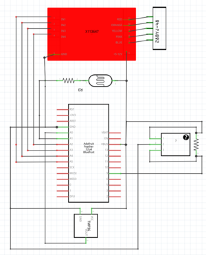
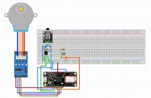
Initially, the temperature sensor, photoresistor, hall effect sensor, and motor were set up individually on the breadboard and tested with the Arduino. After troubleshooting individual threads of code and making sure each component functioned properly in the circuit, the components were set up together on the breadboard. The three legs of the temperature sensor are connected to positive, A0, and ground, respectively. For the hall effect sensor, the left leg of the hall effect sensor connects to a 10k resistor and then to positive, the middle leg connects to the right leg of the temperature sensor and then to ground, and the right leg connects to the other end of the 10k resistor and then to pin 12. One leg of the photoresistor connects to positive, and the other leg connects to one end of another 10k resistor and then to A1. The other end of the most recently mentioned 10k resistor connects directly to negative. For the motor, the gray wire connects to positive, and the brown wire connects to negative. The positive end of the circuit is then connected to 5V, which is labeled as USB on the Feather, and the negative end is connected to ground. This explanation can be clearly seen in the perfboard sketch pictured below. After determining all of these connections, everything was soldered onto the perfboard, along with pins to easily connect to the headers of the feather with jumper wires.
Functioning of Blinds
Using the rotating device located at the top of the blinds, it takes approximately 11 revolutions to open the blinds from 0 degrees (with the flaps completely shut) to 90 degrees (with the flaps parallel to the ground). 11 revolutions is equal to 44,836 steps taken by the stepper motor; therefore, it takes approximately 498.2 steps to move the blinds 1 degree.
3D Printing
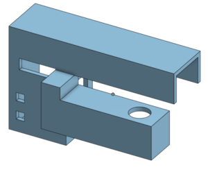
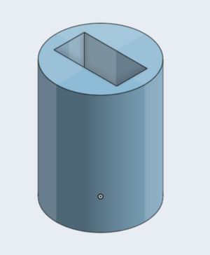
OnShape[1] software was used to design the connector between the blinds and the stepper motor as well as the enclosure for the Feather, perfboard, and motor. The enclosure is designed to easily clamp on and off of the top of any blinds without any messy installation. A circular extrusion from the part of the enclosure that holds the motor and motor driver allows for a connector to be attached between the rotating hook of the blinds and the motor.
Mounting Blinds
For presentation purposes, the blinds were mounted onto a 24" wooden plank using the metal clamps that came with the blinds for mounting. Two 32" planks were connected to each end of the 24" plank, and with this setup, the blinds were hung over the edge of the table with the 24" plank slightly hanging over the edge and the 32" planks on the table used for stability.
Programming
Detecting Temperature of Room
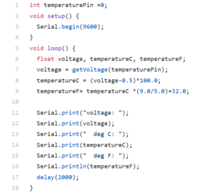
An LM35DX temperature sensor[2] measures the temperature of the room in which the blinds are located. The voltage is detected from the temperature pin, and this value is converted into degrees Celsius and then into degrees Fahrenheit, as seen in lines 7 through 9 of the code.
Detecting Luminosity of Room
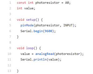
The CdS photocell[3] (photoresistor) detects the amount of light in the room in which the blinds are located. Values read from the photocell are converted to brightness on a scale of 1-5, which was done to prevent user confusion with unfamiliar brightness values.
Receiving User Input
Smarter Blinds are controlled by the Adafruit Bluefruit LE Connect App[4], which is available for free on both iOS and Android devices. Any device can pair with the Adafruit Feather 32u4 on the opening page of the app which connects via the Feather's built-in Bluetooth chip. Once the device is connected to the Feather, the user will click the UART tab. On the bottom of the UART screen is a textbox where the user will be directed to enter their desired room temperature or brightness.
Setting Initial Position of Blinds
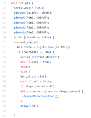
The Hall Effect sensor[5] determines when the blinds are closed. A strong magnet is mounted on the blinds so the blinds are completely closed when the magnet is detected. While the magnet is not detected, the motor is directed to continue rotating the blinds in the counterclockwise direction. Once the magnet is detected the blinds will be closed, which is the desired initial position for calling other functions.
Opening and Closing the Blinds
A 5VDC Stepper Motor is used to rotate the position of the blinds in both clockwise and counterclockwise directions[6]. The stepper motor opens from 0 degrees, letting in no light, to 90 degrees, letting in the maximum amount of light. The stepper motor code directs the motor to move in increments of blind-degrees; therefore, the stepper motor takes 4076 steps in order to move one degree.
Formulas
The user inputs a number from 1 to 5 indicating how bright they would like the room to be. The photoresistor has a max value of 1023. Therefore, the formula for converting the number inputted to a value that corresponds with the photoresistor values is 1023/5 multiplied by the user input value. 5 corresponds to very bright and 1 corresponds to a very dark room.
Another formula created was to correlate the position of the blinds to the brightness desired. The position of the blinds that correlates to the brightest setting is when the blinds are perpendicular to the window letting a maximum level of light pass through. The motor, after initialized moves the blinds 45 degrees then however many more degrees needed to position the blinds at the desired brightness. This formula is steps_needed = (4076 * 5.5) + (5 - bright_scale) * (4076);
For temperature, the blinds are set at an ideal position of slanted downwards at 45 degrees. When the room needs to adjust to a warmer temperature the blinds are at a position of 90 degrees so that max light can open. When the room needs to cool down, the blinds are closed. The temperature revolves around an ideal position of 45 degrees closed.
Electronics
We chose to use the Arduino Feather[7] rather than the Arduino Uno because of the Feather's Bluetooth chip and efficient battery charging capabilities. Since the primary method for controlling the Smarter Blinds is via the Adafruit Bluefruit app, the Feather allowed us to bypass connecting a separate Bluetooth device. Another benefit of the Feather is that it can be powered by a microUSB cable that is plugged into a wall outlet. Therefore, there isn't the worry of running short on power.
Results
We were successful in creating Smarter Blinds that operate based off a user's desired temperature or brightness in a room. The project consists of the components that allow the user to adjust their ideal brightness and temperature in a room using the Bluefruit app via Bluetooth connection. Furthermore, in the temperature setting, the blinds self adjust according to the user's ideal temperature in relationship to the actual temperature. For the brightness, the blinds adjust according to the user's brightness preference, which they select from a scale of 1 to 5. Additionally, if it is dark outside (i.e. the lights are off) the blinds close automatically and then re-open once brightness is achieved again.
In relation to the original objectives, the project still has the blinds moving according to data read from the photoresistor and temperature sensor but has adapted into a more user-based input project and less on time of day.
These blinds would be more accurate in a real-life setting where temperature varies naturally due to sunlight. However, in Lopata Gallery, the amount of sunlight in the room is minimal and as a result, temperature of the area is held constant.
Next Steps
To continue this project, we should attempt to use solar energy as a power source for Smarter Blinds. Using solar energy would allow for the project to be self-powered, and it would also utilize the natural sunlight in yet another eco-efficient way. The current design for the blinds is only applicable for blinds which operate by a rotating stick. However, further developments of our model should be versatile for different types of blinds, such as blinds that are operated by pulleys. Additionally, this project should make adjustments to have the blinds controlled from the Adafruit FeatherWing as well as the Adafruit Bluefruit App. Using the buttons to select the ideal temperature and brightness directly on the FeatherWing would allow for people to control the blinds without using their phone, if desired. One last development that should be added to enhance Smarter Blinds is to develop an efficient way to switch between adjusting temperature and brightness without having to completely reset the blinds.
Regarding security, next steps should be to make the connection between the Adafruit FeatherWing and any device a private connection so that the control of the blinds can not be exploited. Also, a setting should be added to ensure room privacy despite the temperature or brightness of room. This would allow for the blinds to stay closed until the user chooses to open the blinds again.
Resources
- Past Projects
https://classes.engineering.wustl.edu/ese205/core/index.php?title=Smart_Blinds https://www.hackster.io/Froz3nArcher/smart-blinds-573548 https://www.hackster.io/rjacobo2/lane-tech-hs-pcl-iot-smart-blinds-42a68a (potential design idea)
- Stepper Motor and Arduino
Arduino Modules - L298N Dual H-Bridge Motor Controller Controlling DC Motors with the L298N Dual H-Bridge and an Arduino
- Bluetooth Connection
Adafruit Bluefruit LE UART Friend - Bluetooth Low Energy (BLE) Adafruit Feather 32u4 Bluefruit LE Adafruit Feather 32u4 Bluefruit Overview
- Soldering
Soldering YouTube How to Solder
- Temperature Sensor
- Photoresistor
References
- ↑ OnShape 3D Printing https://www.onshape.com/
- ↑ Temperature Sensor https://www.arduino.cc/en/uploads/Main/TemperatureSensor.pdf
- ↑ Photoresistor https://www.electroschematics.com/wp-content/uploads/2012/12/PDV-P8103-ldr.pdf
- ↑ Bluefruit App https://learn.adafruit.com/bluefruit-le-connect/ios-setup
- ↑ Hall Effect Sensor https://www.elecrow.com/download/A3141-2-3-4-Datasheet.pdf
- ↑ Stepper Motor 5V 4-Phase 5-Wire & ULN2003 Driver Board for Arduino http://eeshop.unl.edu/pdf/Stepper+Driver.pdf
- ↑ Arduino Feather 32u4 https://cdn-learn.adafruit.com/downloads/pdf/adafruit-feather-32u4-bluefruit-le.pdf
