Difference between revisions of "MedLit Log"
m (Protected "MedLit Log" ([Edit=Allow only administrators] (indefinite) [Move=Allow only administrators] (indefinite))) |
|||
| (2 intermediate revisions by one other user not shown) | |||
| Line 91: | Line 91: | ||
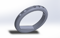
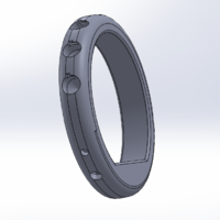
[[File: -Users-moiramulholland-Desktop-pic of bracelet w slot inserts.PNG|200px|thumb|left|Final Bracelet Design]] | [[File: -Users-moiramulholland-Desktop-pic of bracelet w slot inserts.PNG|200px|thumb|left|Final Bracelet Design]] | ||
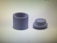
[[File: -Users-moiramulholland-Desktop-pic of cap w insert cylinder.PNG|200px|thumb|center|Final Cap Design]] | [[File: -Users-moiramulholland-Desktop-pic of cap w insert cylinder.PNG|200px|thumb|center|Final Cap Design]] | ||
| + | |||
| + | |||
| + | |||
| + | |||
| + | |||
| + | |||
==4/15/18== | ==4/15/18== | ||
Latest revision as of 12:07, 5 May 2018
Contents
2/1/18
At the beginning of this week we met with our TA, John, and Professor Feher. The two of them helped us to further narrow down our project as far as form factors. Some ideas were thrown around considering making a locket versus a bracelet or wristband. In the middle of the week, our group met to choose exactly how we wanted to design our project. In this meeting, we drew a rough sketch of our project, which we decided would be a bracelet. We considered a necklace and have decided that will be a reach goal once we finish our bracelet. We looked at a variety of microprocessor options and hope to finalize our decision on Friday with John. We will 3D print our bracelet using TPU material, as it slightly flexible. This week we set both our initial goals and our reach goals, and we hope to have our project approved so that we can start ordering parts this upcoming week.
In the upcoming week we hope to finish our Gantt chart, finalize what parts we want, and order our parts. We foresee possible problems in choosing our batteries, LED lights, and microprocessor. We will solve this by sitting down and considering the amount of power the microprocessor and LED lights will use, and considering that when ordering.
2/5/18
We met with our TA, John, again today. We had already created a rough Gantt chart of what we plan to accomplish and when, but still have to assign each deadline to members of our group. We ordered the Tiny AVR Programmer (1), the ATtiny (3), and the battery (1) after calculating the theoretical power consumption of the ATtiny when it runs our intended program. Looking forward, it would be ideal if we could print the bracelet with two different materials. We will need to find a printer with this capability.
We plan to get familiarized with our items when they arrive so that we can demonstrate a working LED by next Friday. We also need to finish the project proposal and our official budget this week.
A possible issue we expect for the coming week or two is getting fully familiarized with our project parts.
2/7/18
At the beginning of our group meeting (no TA) we updated the Gantt chart to assign specific roles to each group member. We have essentially divided our project into three parts for each of us to be in charge of, for the most part. Those three parts are software (Anton), electronics (Moira), and hardware (Lauren). We also took measurements of two different types of birth control pills that are different sizes and will begin sketching our bracelet before we put it in Solidworks in the next two weeks. We want to print our bracelet in the urethane material and create cases out of PLA to sit in that material and hold each pill securely. We will hopefully be getting our materials delivered in the coming week and will be able to mess around with them and become familiar with them.
Our goal for this Friday is to have our budget proposal finalized, and for next Friday it is to have a working LED to demonstrate and finish our proposal powerpoint.
2/14/18
The ATtiny came in the mail along with the programmer and LED lights. Our group met in the lab and downloaded the software necessary to program the ATtiny. We set up a test code to run and see if we can blink the LED. We also drew a much more detailed sketch of what we want the bracelet to look like and what dimensions it needs to have. We will finalize those and put it in Solidworks when we decide how to wire all the electronics inside the bracelet.
Some concerns we have going forward are 3D printing this bracelet with electronics inside and packaging the LEDs into the walls of the bracelet. However, our main goal for this Friday is to have a working LED. We will continue to tinker with the ATtiny this week.
2/16/18
We demonstrated a working LED in class today! This showed that we have become familiar with our LED lights and AtTiny. We, unfortunately, discovered that the crystals in our AtTiny are fairly unstable and we may need to order a RTC so that our timer will be most efficient. This will be an issue we will discuss with our TA in the upcoming weeks as we further work with the AtTiny and decide if the RTC is necessary.
2/23/18
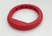
The previous week was a fairly slow week for us as we were all fairly busy. We played around a bit with out LED lights turning them on and off. We also created our proposal presentation and presented that on Friday. In this upcoming week, we will focus on programming the AtTiny to meet our specific bracelet design and look into possible RTCs to purchase. We will also work on connecting our batteries with our LEDs in the way that we intend to set up in our bracelet. Lastly, we will focus on researching solutions to check the battery life of our bracelet's battery. We plan to accomplish all of this within the next two weeks. Below is a preliminary bracelet we printed that shows the flexibility of bracelets when designed in specific geometric ways.
3/02/18
This week we re-familiarized ourselves with solid works. We also spent some time online researching some designs for screw on caps and possible ways of modeling them. Below is a picture of our current solid works model of a screw compartment. In this upcoming week, we plan to print and edit a few version of screw on cap compartments which we will use to hold our pills. We will also begin to attach our electronics and design various compartments to fit our battery, wires, LED lights, and AtTiny so that when we print out bracelet we have one compact compartment of our electronics to fit into it. We foresee a LOT of trial and error when designing our capsules and the screw on cap. However, once the screw on caps are done and the electronics are in a compact box we will be able to focus on printing a bracelet around it.
Reference Link to use when designing screw on cap
Some possible charge checks can be found in the following link. As we finish programming our AtTiny we will look into choosing one of the following state of charge checks and which will work bester for our project.
Reference Link to use when choosing State of Charge Check
3/19/18
Over the past few weeks we began modeling everything on solid works. As seen above, we designed a capsule for the pill. We then designed a preliminary bracelet on solid works. One issue we encountered we forming holes in the bracelet. We designed one horizontal plane (parallel with bottom of your wrist) and cut three holes through the top. Then we designed a plane perpendicular to this plane and cut two holes in each direction forming our last four holes. We found this to be the simplest way to model our holes that we will place out capsules in. However, we worry the slight angles as the bracelet curves will make the capsules extrude in a clunky way. In this case, we may need to cut our holes using a slightly differently angled plane for each hole. After discussing with TA Nathan the idea we had for our capsules he suggested it might be easier to buy a nut and bolt set from Home Depot to use as our capsules instead. This week we will head to home depot and check out the options for a nut and bolt set so as to avoid all the issues of 3D printing a small screw on cap. Some challenges this week include finding the nut and bolt set as well as properly designing our bracelet to fit this set. In the upcoming week we will search for a nut and bolt set, edit our bracelet, begin printing our preliminary bracelet model, and begin connecting all of our electronic parts together.
3/19/18
Our trip to Home Depot was unsuccessful as the nut and bolt we were looking for was not something they carried. Instead we think we will try A.C. Moore for this nut and bolt but we will also work on our second idea which is the use of a rubber material to almost wedge the pills in the case into the holes of the bracelet. This would take a lot of trial and error, as we would really need to consider usability since we don't want the pills to break or fall out from any vigorous movement. However, we successfully printed our first bracelet. Some changes that will be made to it include: hollowing out the base for the electronics to sit, expanding the holes for the pill cases, and printing it with a more flexible material. Other than the prior list, we found our first print to be fairly successful.
3/31/18
This week we worked further on the design of our bracelet. We decided to close off the holes on the inside of the bracelet so that it will lay flat against our wrists and then a stopper will be placed on the top to push the bracelet in. However, this was tough because of the way in which we made our bracelet holes. We designed holes in the middle plane and then extruded cut holes through the entire surface. This lead to some holes being angled in a weird way. After some research we discovered the Hole Wizard function which allowed us to cut holes normal to each side of the rounded bracelet into the bracelet, stopping right before cutting all the way through. This was a huge breakthrough for us as with our original holes we made another surface on the bottom to cover up the bottom holes which created some uncomfortable edges on the bracelet, which we discovered when we printed it. We also printed a bracelet with an open surface on the bottom so as to see how our ATTiny will fit. Unfortunately, we must have measured something wrong as our AtTiny was just slightly too wide for the hole. We then went back to our bracelet and redesigned its thickness so it will fit the AtTiny. We then added space for all the electronics including a hole for the LED to stick out of. We lastly were able to set up our light with our battery and our ATTiny and we successful in lighting up the LED.
Plans for our upcoming week:
- finish a cap design
- finish connecting and soldering our electronics together
- place our electronics into our bracelet
4/4/18
Today we met with Professor Mell to discuss our project progress. We decided we need to make some type of insert that will hold the cap in the pill case on the bracelet in a more sturdy way. We also discussed adding a resistor to our circuit because we hadn't previously thought about limiting the charge going to our LED.
4/8/18
At this point in time, the electronics are almost fully complete. The finial circuit will consist of the ATTiny, two 312 coin cell batteries, a 5mm LED, a reset button, and a resistor. The software needs to be modified so that the reset button will reset the timer once the pill is taken.
4/10/18
Today we implemented a new design for the holes/pill cases. We added an L shaped indent to the side of each hole. Then on the cap parts, we added a circular knob that sticks out of the side. That knob will fit into the L shaped insert and the user will twist the cap so that the it is more tightly stuck in the pill case. We are printing this later this week to make sure it fits.
We also finished the code that will allow the timer to reset for another 24 hours after the light goes off. We still need to work on connecting the button to this, and we aim to get that done before Friday.
4/15/18
At this point in time, the bracelet has been fully printed with PLA multiple times and design changes have been considered. The print takes about 30 min but overall time depends on density and resolution. At the end of the day we plan to either print with TPU or use SLA and flexible resin.
4/16/18
We have tried printing the bracelet with TPU 6 times without any success. The printers that we have access ideally need modifications to print with TPU. Imagine trying to force cooked spaghetti into a hole of the same diameter. It ends up buckling and ultimately getting caught in the drive gears. Therefore, we are going to go the route of flexible resin.
4/18/18
The bracelet has been successfully printed using flexible resin. It is in three different pieces. We have inserted the electronics and glued the pieces together. Inherently, the resin is pretty brittle and is definitely not the ideal solution. But, it will most certainly suffice for demonstration purposes.
4/19/18
To add to the value of our demo, we have printed a single bracelet with the electronics embedded. This was done with PLA, the print was paused, electronics placed, and print resumed. It turned out nicely.


