Difference between revisions of "Cycle Charger"
m (Protected "Cycle Charger" ([Edit=Allow only administrators] (indefinite) [Move=Allow only administrators] (indefinite))) |
|||
| (43 intermediate revisions by 2 users not shown) | |||
| Line 1: | Line 1: | ||
| + | = <big>'''Project Proposal'''</big> = | ||
== <big>'''Overview'''</big> == | == <big>'''Overview'''</big> == | ||
Energy is all around us, but on a near daily basis we find ourselves low on charge by the end of the day. The objective of Cycle Charger is to harness the rotational energy of a bicycle ride and store the energy in a battery for a late day boost. Cycle Charger aims to be completely out of the way, requiring no user input beyond riding and plugging in. | Energy is all around us, but on a near daily basis we find ourselves low on charge by the end of the day. The objective of Cycle Charger is to harness the rotational energy of a bicycle ride and store the energy in a battery for a late day boost. Cycle Charger aims to be completely out of the way, requiring no user input beyond riding and plugging in. | ||
| Line 37: | Line 38: | ||
Permanent Magnets - given<br /> | Permanent Magnets - given<br /> | ||
Insulated Wire - given<br /> | Insulated Wire - given<br /> | ||
| − | [https://www.amazon.com/KBP06-RS205-Full-Bridge-Rectifier/dp/B01B3K569A/ref=sr_1_13?ie=UTF8&qid=1518047239&sr=8-13&keywords=bridge+ | + | [https://www.amazon.com/KBP06-RS205-Full-Bridge-Rectifier/dp/B01B3K569A/ref=sr_1_13?ie=UTF8&qid=1518047239&sr=8-13&keywords=bridge+rectifier Full Wave Bridge Rectifer x 5 - $6.99]<br /> |
[https://www.amazon.com/UNITED-ESMH500VNN682MP50T-Aluminum-Electrolytic-Capacitor/dp/B073477247/ref=sr_1_2_sspa?s=industrial&ie=UTF8&qid=1518140153&sr=1-2-spons&keywords=6800uf+capacitor+50v&psc=1 50V, 6800uF Capacitor x 5 - $14.57]<br /> | [https://www.amazon.com/UNITED-ESMH500VNN682MP50T-Aluminum-Electrolytic-Capacitor/dp/B073477247/ref=sr_1_2_sspa?s=industrial&ie=UTF8&qid=1518140153&sr=1-2-spons&keywords=6800uf+capacitor+50v&psc=1 50V, 6800uF Capacitor x 5 - $14.57]<br /> | ||
[https://www.amazon.com/Aibocn-External-Battery-Charger-Flashlight/dp/B00VWV8LD4/ref=sr_1_5?ie=UTF8&qid=1518141116&sr=8-5&keywords=portable%2Bcharger&th=1 Portable Charger - $9.99]<br /> | [https://www.amazon.com/Aibocn-External-Battery-Charger-Flashlight/dp/B00VWV8LD4/ref=sr_1_5?ie=UTF8&qid=1518141116&sr=8-5&keywords=portable%2Bcharger&th=1 Portable Charger - $9.99]<br /> | ||
PVC Pipe for the case holding dynamo<br /> | PVC Pipe for the case holding dynamo<br /> | ||
Metal Brackets for attaching the dynamo and battery to the bicycle <br/> | Metal Brackets for attaching the dynamo and battery to the bicycle <br/> | ||
| + | |||
| + | = <big>'''Design and Solutions'''</big> = | ||
| + | == <big>'''Necessary Materials'''</big> == | ||
| + | To start off our project construction, we had to acquire the following materials: | ||
| + | * PVC Pipe (for outside casing) | ||
| + | * 2 PVC end caps | ||
| + | * Metal on Plastic Epoxy | ||
| + | * 1 metal dowel rod (to be used for axle) | ||
| + | * Spool of thin copper wire | ||
| + | * Iron frame (horseshoe shaped) | ||
| + | * Connecting wires | ||
| + | * Perf board for circuitry | ||
| + | * 4 diodes (for rectifier) | ||
| + | * Capacitors | ||
| + | * 2 magnets | ||
| + | * Delrin rings (to prevent overheating of moving parts) | ||
| + | Majority of these items were purchased at the local home depot while others were provided in lab. We also used a number of power tools including; power drill, table saw, power sander (all provided by the upstairs machine shop). The ESE 205 lab also provided soldering equipment, which was extremely useful. | ||
| + | |||
| + | == <big>'''Procedure'''</big> == | ||
| + | '''3D Printing'''<br /> | ||
| + | Construction began with sizing all appropriate materials to the correct size and 3D printing all the necessary parts. Team member Kyle Cummings designed and printed an axle cover to hold the rotating magnets in place. Small wedges were also printed to better secure the magnets within the axle casing. | ||
| + | <gallery> | ||
| + | Cycle_Charger_Drawing.PNG|Full drawing of part on CAD software. | ||
| + | Cycle_Charger_Part.PNG|View of part before printing. | ||
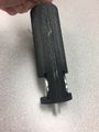
| + | Axle.JPG|Completed axle. | ||
| + | Axle_mag_view.JPG|Axle holding magnets. | ||
| + | Wedges.jpg|Wedges inserted into axle. | ||
| + | </gallery> | ||
| + | We inserted the wedges along the sides of each magnet and this proved very effective. This solved one of our challenges of ensuring that vibrations due to riding the bike would not throw off correct rotation patterns. | ||
| + | |||
| + | '''Frame Constuction'''<br /> | ||
| + | The next step tackled was coiling our copper wire around the iron frame. To prevent scratches and potential tears in the wire due to the pressure of wrapping, all edges of the iron were covering with electrical tape. About 2 hours of wire wrapping finally completed the piece. However, we then realized that we needed a hole in the middle of the frame to place the axle in. So we unwrapped the wire, drilled a 5/16 inch hole in the frame’s middle, and proceed to rewrap the wire (avoiding covering our newly drilled hole). Knowing the nature of metal moving on metal, we decided to place a delrin ring in the drilled hole to prevent the moving axle from overheating. | ||
| + | <gallery> | ||
| + | Frame_delrin_hole.JPG|Raw frame with delrin hole. | ||
| + | Wire_wrapped.jpg|Frame wrapped with copper wire. | ||
| + | Wrappedwrie.JPG|Testing current. | ||
| + | </gallery> | ||
| + | We experimented by spinning the axle with our magnets attached over the wire covered frame. Now, we were limited to the speed of our spinning because our only method was spinning by the use of hands, but a connected multimeter still showed generated current. So we knew we were moving in the right direction. | ||
| + | |||
| + | '''Circuitry'''<br /> | ||
| + | After the successful construction of the frame of our project, it was time to move onto the circuitry. To prevent differences in voltage across the circuit turning our generator into a motor, we needed to use a rectifier. After reading stats online and testing rectifiers in lab, we came to the conclusion that for our specific situation we would need to construct our own. Research was done and a full bridge rectifier was build. This consisted our 4 diodes and was soldered into our perf board. Aligning the diodes correctly ensured that our generated current would only flow one way and not come back on the alternator, making it more difficult to operate. But because of the nature of starting and stopping the riding of a bike, we knew there would be large fluctuations in our generated current. So we decided to incorporate a 1000 µF capacitor to better control these fluctuations and keep our current moving at a more steady rate that wouldn’t damage the surrounding components (i.e the chargeable battery). This was connected to our circuitry and soldered into our perf board alongside the rectifier. After multiple tests using the multimeter, we concluded that our circuitry accomplished what was necessary for the Cycle Charger. | ||
| + | <gallery> | ||
| + | Soldering.JPG|Soldering components together. | ||
| + | completed_perf.jpg|Completed perf board with rectifier and capacitor. | ||
| + | </gallery> | ||
| + | |||
| + | '''Final Construction'''<br /> | ||
| + | Each component of the design was epoxied and secured into place to prevent moving due to vibrations and strategically placed into the PVC casing. We basically layered our project like parts of a sandwich: two PVC end caps being the outside buns, and the perf board and wire-coiled iron frame being the meat and the cheese. Then we skewered the entire thing with our rotating axle dowel rod and 3D printed casing holding the magnets. We slid several delrin rings around the central axel to mitigate friction and unwanted movement. Two wires led to the outside of our casing to allow for hookup of the multimeter and eventually our chargeable battery. This concluded the construction of the Cycle Charger and it was prepared for presentation. | ||
| + | <gallery> | ||
| + | New_picture.jpeg|Components ready to be expoied. | ||
| + | </gallery> | ||
| + | |||
| + | = <big>'''Final Results'''</big> = | ||
| + | == <big>'''Outcome'''</big> == | ||
| + | Final testing with the multi-meter showed that our alternator generated around 12 volts unregulated. We were pleased with this outcome as it allowed us the ability to charge/power much larger things than we expected. The necessary voltage to charge our portable battery is 5 volts and we surpassed that minimum and were not limited to only having one project outcome. | ||
| + | |||
| + | == <big>'''Potential Improvements'''</big> == | ||
| + | Overall, the project was successful with minimal complications along the way. We were effective in accomplishing our goals proposed in the beginning of the semester. | ||
| + | With additional time, we would like to design Cycle Charger to be more practical in real life situations. This includes decreasing the size and therefore decreasing the input costs of construction. Our current model is a bit large and doesn’t very easily fit a bike. However, this model allows for quick modification to accommodate the resizing plan. The large size was helpful for wiring and designing mechanics when we were still discovering how everything should operate. Now, as seasoned engineers, we could easily replicate the process and more efficiently allocate our resources. | ||
== <big>'''Relevant Tutorials'''</big>== | == <big>'''Relevant Tutorials'''</big>== | ||
| − | https://classes.engineering.wustl.edu/ese205/core/index.php?title= | + | *[[Disassemble_an_iPhone_Charging_Block|How to Disassemble an iPhone Charging Block]] |
| + | *[https://classes.engineering.wustl.edu/ese205/core/index.php?title=Full_Bridge_Rectifier_Assembly#Assembly|Full Bridge Rectifier Assembly] | ||
| + | |||
| + | == <big>'''Project Poster'''</big> == | ||
| + | [[File:2018-05-01 (2).png|764px]]<br/> | ||
| + | * Poster was presented in Lopata Gallery on 4/20/18 | ||
| − | + | = <big>'''Weekly Log Link'''</big> = | |
[[Cycle_Charger_Weekly_Log|Link to Weekly Log]] | [[Cycle_Charger_Weekly_Log|Link to Weekly Log]] | ||
Latest revision as of 12:02, 5 May 2018
Contents
Project Proposal
Overview
Energy is all around us, but on a near daily basis we find ourselves low on charge by the end of the day. The objective of Cycle Charger is to harness the rotational energy of a bicycle ride and store the energy in a battery for a late day boost. Cycle Charger aims to be completely out of the way, requiring no user input beyond riding and plugging in.
Team Members
- Kyle Cummings
- Nathan Genstein
- Kaylynn Williamson
- Sam Chai (TA)
Objectives
Generate:
- Through the use of a "bottle dynamo" we will use the rotation of the wheel of the bike to rotate magnets in the presence of a copper coil to generate electricity.
Convert:
- Using a "rectifier" we will convert the AC current created from the generator into DC current. Then a capacitor will be used to generate smooth current that a phone can use.
Store:
- We will then feed the generated current into a battery that is fastened to the bike where it will be stored. There will also be a detachable portable charger that will be charged from the main battery.
Challenges
- Learning how to properly assemble a bottle dynamo.
- Sizing the components of the bottle dynamo properly to avoid friction/ rapid unscheduled disassembly.
- Fastening the components to the bicycle in such a way that the wires won't come loose with the vibration of the bike.
- Wiring the battery in such a way that the fluctuation in the energy generation does not damage the components.
- Figuring out how to not make the generator overheat
- Prevent the alternator from inadvertently becoming a motor from the battery.
Gantt Chart
Link to Gantt Chart Spreadsheet

- Note This may not be updated. For an up to date version click the link.
Budget
Copper Wire - given
Iron Core - given
Permanent Magnets - given
Insulated Wire - given
Full Wave Bridge Rectifer x 5 - $6.99
50V, 6800uF Capacitor x 5 - $14.57
Portable Charger - $9.99
PVC Pipe for the case holding dynamo
Metal Brackets for attaching the dynamo and battery to the bicycle
Design and Solutions
Necessary Materials
To start off our project construction, we had to acquire the following materials:
- PVC Pipe (for outside casing)
- 2 PVC end caps
- Metal on Plastic Epoxy
- 1 metal dowel rod (to be used for axle)
- Spool of thin copper wire
- Iron frame (horseshoe shaped)
- Connecting wires
- Perf board for circuitry
- 4 diodes (for rectifier)
- Capacitors
- 2 magnets
- Delrin rings (to prevent overheating of moving parts)
Majority of these items were purchased at the local home depot while others were provided in lab. We also used a number of power tools including; power drill, table saw, power sander (all provided by the upstairs machine shop). The ESE 205 lab also provided soldering equipment, which was extremely useful.
Procedure
3D Printing
Construction began with sizing all appropriate materials to the correct size and 3D printing all the necessary parts. Team member Kyle Cummings designed and printed an axle cover to hold the rotating magnets in place. Small wedges were also printed to better secure the magnets within the axle casing.

Full drawing of part on CAD software.

View of part before printing.
Completed axle.

Axle holding magnets.

Wedges inserted into axle.


We inserted the wedges along the sides of each magnet and this proved very effective. This solved one of our challenges of ensuring that vibrations due to riding the bike would not throw off correct rotation patterns.
Frame Constuction
The next step tackled was coiling our copper wire around the iron frame. To prevent scratches and potential tears in the wire due to the pressure of wrapping, all edges of the iron were covering with electrical tape. About 2 hours of wire wrapping finally completed the piece. However, we then realized that we needed a hole in the middle of the frame to place the axle in. So we unwrapped the wire, drilled a 5/16 inch hole in the frame’s middle, and proceed to rewrap the wire (avoiding covering our newly drilled hole). Knowing the nature of metal moving on metal, we decided to place a delrin ring in the drilled hole to prevent the moving axle from overheating.

Raw frame with delrin hole.

Frame wrapped with copper wire.

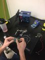
Testing current.


We experimented by spinning the axle with our magnets attached over the wire covered frame. Now, we were limited to the speed of our spinning because our only method was spinning by the use of hands, but a connected multimeter still showed generated current. So we knew we were moving in the right direction.
Circuitry
After the successful construction of the frame of our project, it was time to move onto the circuitry. To prevent differences in voltage across the circuit turning our generator into a motor, we needed to use a rectifier. After reading stats online and testing rectifiers in lab, we came to the conclusion that for our specific situation we would need to construct our own. Research was done and a full bridge rectifier was build. This consisted our 4 diodes and was soldered into our perf board. Aligning the diodes correctly ensured that our generated current would only flow one way and not come back on the alternator, making it more difficult to operate. But because of the nature of starting and stopping the riding of a bike, we knew there would be large fluctuations in our generated current. So we decided to incorporate a 1000 µF capacitor to better control these fluctuations and keep our current moving at a more steady rate that wouldn’t damage the surrounding components (i.e the chargeable battery). This was connected to our circuitry and soldered into our perf board alongside the rectifier. After multiple tests using the multimeter, we concluded that our circuitry accomplished what was necessary for the Cycle Charger.
Soldering components together.

Completed perf board with rectifier and capacitor.


Final Construction
Each component of the design was epoxied and secured into place to prevent moving due to vibrations and strategically placed into the PVC casing. We basically layered our project like parts of a sandwich: two PVC end caps being the outside buns, and the perf board and wire-coiled iron frame being the meat and the cheese. Then we skewered the entire thing with our rotating axle dowel rod and 3D printed casing holding the magnets. We slid several delrin rings around the central axel to mitigate friction and unwanted movement. Two wires led to the outside of our casing to allow for hookup of the multimeter and eventually our chargeable battery. This concluded the construction of the Cycle Charger and it was prepared for presentation.

Components ready to be expoied.

Final Results
Outcome
Final testing with the multi-meter showed that our alternator generated around 12 volts unregulated. We were pleased with this outcome as it allowed us the ability to charge/power much larger things than we expected. The necessary voltage to charge our portable battery is 5 volts and we surpassed that minimum and were not limited to only having one project outcome.
Potential Improvements
Overall, the project was successful with minimal complications along the way. We were effective in accomplishing our goals proposed in the beginning of the semester. With additional time, we would like to design Cycle Charger to be more practical in real life situations. This includes decreasing the size and therefore decreasing the input costs of construction. Our current model is a bit large and doesn’t very easily fit a bike. However, this model allows for quick modification to accommodate the resizing plan. The large size was helpful for wiring and designing mechanics when we were still discovering how everything should operate. Now, as seasoned engineers, we could easily replicate the process and more efficiently allocate our resources.
Relevant Tutorials
Project Poster
.png)
- Poster was presented in Lopata Gallery on 4/20/18