Difference between revisions of "The Solver"
Alexherriott (talk | contribs) (→Mechanical: Added final design description) |
|||
| Line 91: | Line 91: | ||
==Results== | ==Results== | ||
===Final Results=== | ===Final Results=== | ||
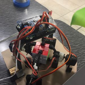
| + | [[File:Rubik's Cube.JPG|thumbnail|left|This is our final design for the solver]] | ||
| + | |||
===Difference From Original=== | ===Difference From Original=== | ||
===Interference=== | ===Interference=== | ||
Revision as of 17:44, 5 May 2016
Contents
Project Overview
The robot should be able to take any scrambled rubik's cube and solve it without any input from outside systems, as in, all computation must happen on the microcontroller itself. It will do this by first using a camera to identify the colors on each side of the cube before plugging that input into a solving algorithm. Finally, using the solution generated, it will manipulate the cube using four grippers around the cube. Each of which will be able to both rotate the nearest face or the entire cube itself.
Team Members
- Oscar Arias
- Jordan Aronson
- Alex Herriott
- Deko Ricketts (TA)
Objectives
To build this, we need these things:
- 1. Build a robot which includes a Raspberry Pi along with motors that can rotate parts of the cube horizontally and vertically.
- 2. Create code to take the set of instructions and give them to the robot which will execute the necessary moves to solve the cube.
- 3. Create code to detect the colors on a cube on each of its sides
- Backlight the camera
- 4. Convert an algorithm to solve a cube into Python and produce a set of instructions based on its given colors
- 5. Connect the Raspberry Pi to the motors using circuitry
Challenges
Challenges that we predict:
Mechanical
- Designing grippers able to grasp and rotate the cube. It's unlikely we will be able to grip the cube with the surface with PLA filament, so we need some sort of foam surface to provide traction. We also need to make sure that when the cube is released by the gripper it is able to freely rotate.
- Ensuring the grippers rotate exactly 90 degrees so the cube can rotate cleanly and subsequent moves will be able to be performed. Given we are using stepper motors, ensuring that the position of the steppers is zeroed before we start performing moves is important.
- Trying to get the individual moves to take as little time as possible. The steppers that we are considering are relatively high torque and low power
- Designing a convenient way for the cube to be inserted into the device and exit the device. We could possibly use some kind of platform on a screw that is able to raise and lower the cube out of the device.
- Designing circuitry to connect the Pi (The Pi can’t deliver enough power or pins to drive all the necessary servos and steppers) Right now the servos will need one pin each (4 pins total) and the steppers need 4 pins each (16 pins total) that is a total of 20 pins, and the Pi has 17 GPIOs. We need a different method for driving the steppers than the ULN2003 drivers that come with them, or additional circuitry to drive all the inputs. For now we will try and drive the ULN2003 boards with two 8 bit shift registers, which will use 4 pins total, with the servos, that totals 8 pins. however, we are then limited in step speed, which may mean we have to invest in additional hardware, like the Adafruit motor HAT.
- Finding a way to power both the Pi and the actuators from a wall adapter.
CS
- Finding a suitable open source algorithm that we can adapt to our robot to solve the cube.
- Making sure the camera can distinguish the color patterns on each side of the cube and store each face's patterns to memory. We also may be able to detect the colors with the grippers in the way, we may not. That will require some experimentation.
- Design code that can take that algorithm and translate it to what the robot can do. (The robot’s current design can only act on 4 faces at any given time. To access the other two, the cube must be rotated). We must make sure we know the position and orientation of the cube at all times so we know where to go next for our next action.
Budget
- Raspberry Pi — From lab - This is the brains of the operation. It both computes the algorithm to solve the cube and sends commands to the servos.
- Camera (Arducam) — $14.99 - This camera should be able to recognize the colors on the cube to put them into the algorithm.
- Gripper rotation servos - $27.99 - These servos rotate the grippers, turning the faces on the cube.
- Servo driver hat - $23.53 - This is our servo motor controller, capable of taking input from the pi and turning it into servo rotation.
- Servo motors — $11.98 - these mini servos are the actuators for the individual grippers.
- 1" #5 machine screws - used for assembling the build.
- Lab power supply
- Total: $78.49 + $0 shipping (purchased through Amazon prime)
Gantt Chart
Design and Solutions
Mechanical
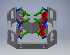
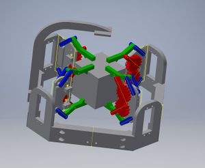
- In our current design we have 4 end effectors on the cube that can rotate one side of the cube. These can therefore turn 4 sides of the cube from any position. The remaining two sides can be accessed by disengaging two of the grippers and rotating the entire cube to a new position.
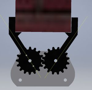
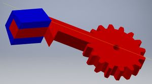
- The grippers that grip the cube will be operated by a mini servo mounted into the base of the gripper and then those grippers will be mounted to stepper motors. By using stepper motors, we are able to get continuous rotation on the grippers and accurate positioning.
- 2/28/16: Design with parts dimensioned and adjusted for the parts now they've arrived. Once the grippers and mounts are assembled we should be able to correctly dimension the edges to hold the mounts together and design a simple camera rig.
- A good amount of time was spent centering each of our wrist servos and ensuring that they rotate exactly +/-90 degrees from center.
- Final design:
- We scrapped the borders around the edges and fixed the servo mounts directly to a piece of acrylic. This was mostly a time-saving measure, but also allowed us to adjust the relative positions of each of the mounts without having to print new pieces.
- The gripper designs went through some major changes. First and foremost, the original design contained a lot of moving parts and had a lot of lateral movement, which resulted in imprecision in rotating the cube. This was replaced with a much simpler two-part system. Grip pads were fitted to the finger tips so increase friction on the cube. Finally, we burned out our micro-servos driving the fingers, so we replaced them with standard size servos to provide more strength and reduce overheating.
Electrical Integration
Learning Raspberry Pi
Instructions for Noobs setup: Noobs Setup
Learning Raspberry Pi was not as easy as it seems. Having never used one before, we followed the instructions listed on their website. However, the instructions were not that specific and we ended up downloading only Raspbian to one of the Raspberry Pi's instead of the entire N00BS package. This ended up being not a problem because Raspbian still had python and everything else we needed. We had to teach ourselves python. We choose the Raspberry Pi because it could successfully use things like OpenCV.
Solving Algorithm
The solving algorithm we used for this project: Pycuber Solving Algorithm
This code executes a commonly known solution algorithm called OLL PLL. While having code that we took from online helped a lot, that was not all we needed to do for the solving algorithm. We had to dissect the code that was written and determine how to successfully input a specific cube and output its solution. Once we did that, all we had to do was create code that would loop through the solution and look at the first 2 to 3 characters depending on the move. Once it had executed that move, delete those 2 or 3 characters and start again. The reason the move could be 2 or 3 characters was because a move could either be "R" or "R'", denoting R inverse, or "R2", denoting to do the R move twice. To output the solution, we had to import the solving algorithm from a different folder of the Pi. Finally, we connected this code with the Motor Control algorithm so that the moves could be executed.
Motor Control
The instructions we used to install the Adafruit servo hat: Learn Adafruit
To control the motors we used the Adafruit servo hat, which comes with code for setting a certain servo to a certain position. We tested each servo to see what number value corresponded to a certain position. We created a list of functions that would execute certain moves on the cube by rotating, grabbing, and releasing. We also created a function to rotate the cube and take multiple pictures of the cube for use in color recognition. Rotating the cube successfully took multiple attempts because the cube would originally drop when we rotated it by releasing two of the grippers, and then turning the other two grippers.. With the stronger servos, we ended up rotating the cube by releasing two of the grippers, and then turning the other two grippers.
Color Recognition
In order to determine the configuration of the Rubik’s cube, we first had to allow the system to recognize what the color of the squares were on each face of the cube. We were able to implement this feature using Arducam, a raspberry pi camera. The camera was positioned above the cube and then used to take a picture of each cube face. The images were then analyzed by setting targets on each of the squares on the face. The pixels at each of the targets were then read directly and converted into numerical values. These values were passed through conditionals which analyzed the red, green, and blue values of the pixels in order to determine what the color of a given square was. After being passed through the code, each pixel set on the square was assigned a value to identify it as one of the six colors on the cube.


