Difference between revisions of "Smarter Blinds Log"
Lkaniewski (talk | contribs) |
|||
| Line 168: | Line 168: | ||
*Designed connector from blinds to motor, sent to Michael for 3D printing | *Designed connector from blinds to motor, sent to Michael for 3D printing | ||
(3 hours) | (3 hours) | ||
| + | |||
| + | March 1 Continued: | ||
| + | *Wrote code that made the motor turning as a function so that it can be called in the main body of the code. It works so that there is a number of steps and once the code iterates that many times the motor stops turning | ||
| + | *Wrote code and tested it so that when the photoresistor value drops below a certain number the motor turns i.e. acting to close blinds. Tested on bread board and was successful | ||
| + | (2.5 hours) | ||
== Week of March 4 == | == Week of March 4 == | ||
Revision as of 22:00, 1 March 2019
Smarter Blinds Log
Contents
- 1 Week of January 14
- 2 Week of January 21
- 3 Week of January 28
- 4 Week of February 4
- 5 Week of February 11
- 6 Week of February 18
- 7 Week of February 25
- 8 Week of March 4
- 9 Week of March 11
- 10 Week of March 18
- 11 Week of March 25
- 12 Week of April 1
- 13 Week of April 8
- 14 Week of April 15
- 15 Week of April 22
- 16 Week of April 29
- 17 Link to Project page
Week of January 14
January 18: Met with Jim and TA's to discuss possible project ideas. 1 hour
Week of January 21
January 22: Met as a team and created first draft of project proposal. Decided on the Smarter Blinds idea basing it of off the previous Smart Blinds project. Further research allowed us to discover other similar smart blind projects. 1 hour
January 27: Created project wiki page and started logging our progress and updating our goals. Created our first draft of our budget and started thinking about our Gantt Chart. 1 hour
Week of January 28
January 28: Met as a team with Professor Feher and Michael to discuss progress. Learned how to create Gantt Chart. Discussed possibilities of using either Arduino with a Bluetooth chip or Feather. Received Arduino device. Briefly went over Night Light project. 30 minutes
January 29: Added tasks to Gantt Chart, basing them primarily off of the Gantt chart from the previous Smart Blinds project. Found and reviewed similar smart blinds projects from hackster.io, such as smart blinds that responded to ambient light and heat as well as smart blinds controlled by Blynk. 1 hour
January 30:
- Constructed a budget for the Night Light project using an Excel spreadsheet. 30 minutes
- Met as a team and continued to work on budget for blinds and Gantt Chart. Finalized proposal and added our expected challenges and goals for our project. We will continue to research for our project and make sure we have finalized the budget and have included all of the necessary parts. Next we will work on the Nite Light Project as well. 1 hour.
January 31:
- Finalized Budget by comparing to past projects and cross checking to make sure all of the correct parts were listed. Currently under the budget of $150 dollars. A decision we had to make was if we wanted to use the Arduino Uno and purchase the Adafruit Bluefruit LE UART Friend - Bluetooth Low Energy (BLE) or use the Adafruit Feather 32u4 Bluefruit device. The Feather was priced at $29.95 while the Arduino Uno + Bluefruit Le UART Friend cost a total of $39.50 (22 +19.50 respectively). The Feather is an all in one device with no need for a bluetooth component. However, with our current access to an Arduino Uno and the wide breath of resources available related to the Arduino Uno and blinds, we decided to go with the combination of the UNO and bluetooth component. Both parts are able to connect to the Adafruit app. Further research of the bluetooth component resulted in finding resources on how to attach the bluetooth component to the breadboard by soldering.
- In preparation for the Nite Light project more research was conducted on soldering and on how to connect items to a breadboard. Links on how to solder and research done on the bluetooth capabilities was added to the Resources section of the main project page.
- Soldering is establishing good connections between components and in order to ensure good connections are made, it is important that we know how to solder correctly so that we do not ruin any parts. It is important to not touch the soldering iron for more than 2 seconds so that the part does not over heat. Once the tip is touching the connection then the solder touches the iron and the iron is pulled away leaving a cone like shape of metal on the connection. It is important to do it correctly to avoid a "cold-solder" that can occur. It is also important to have the iron on one side of the wire and then put the solder on the other side of the iron to make a good connection. At the end the solder should be shiny. 1 hour
February 3: Discussed plan for upcoming week and reviewed Gantt Chart (30 minutes)
Week of February 4
February 6: Got led to blink using Arduino. Followed along youtube video, Blinking LED. Code:
- define LED 13
void setup() {
pinMode(LED, OUTPUT);
} void loop() {
 digitalWrite(LED,HIGH);
 delay(1000);
 digitalWrite(LED,LOW);
 delay(1000);
}
Started working on Nite Light Project. Was able to start on breadboard and get both LED's to light up. Due to material mishaps the goal for the rest of the week is to finish the circuit on the breadboard and plan out how to put it on the perf board and get switch working. Also started learning how to use OnShape. Goal for next week is to print enclosure. 2.5 hours
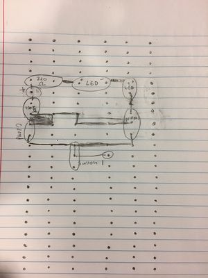
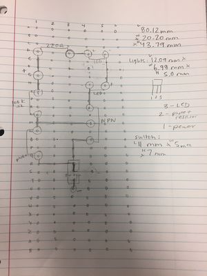
February 8: Finalized breadboard, sketched perfboard plan with soldering lines. Waiting on new PNP transistor to begin soldering next week. Planning to order majority of Smarter Blinds materials on Monday.
Wrote input based code for blinking LED.
1.5 hours
Created presentation template and made outline for everything that presentation should include. 30 minutes
Added to first draft of presentation, planning to get presentation evaluated tomorrow at meeting with Professor Feher and Michael to see what edits we need to make. 1 hour
Week of February 11
February 11
- Ordered light sensor and reserved Adafruit parts at micro center.
- Goals for this week: Finish Night Light, spread out perf board, solder perf board, and build box
- Next goal:start working with the photoresistor and Arduino Uno
(1 hour)
February 12
- Went to Micro Center to pick up parts
(1 hour)
February 13
- Spread out perf board sketch, soldered parts onto perf board, solder-bridged parts together correctly to have a functioning night light
- Took measurements for 3d enclosure
- Goal for the rest of this week: Use OnShape to design box, brainstorm code for Smarter Blinds
(2 hours)
February 15
- Watched another OnShape tutorial and designed enclosure for night light. Goal is to have it 3D printed by Monday. Design process was more complicated than expected.
- Presented Smarter Blinds pitch (hour of class not included in log)
(3 hours)
February 17
- Created simple code to test for moving the stepper motor and receiving values from the photoresistor and temperature sensor
- Researched more potential design ideas and brainstormed potential designs
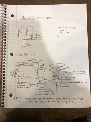
- Created a flow chart regarding the stages of the blinds being open, opening, closing and closed
- Goals for the coming week are to test out the code and continue to build the code for each of the components
(1.5 hours)
Week of February 18
- Tested code and was able to get the motor to move and read photo-resistor values
- Working to build code that uses user input
- Discussed design for the shield and output for the user
(2 hours)
February 22
- Worked to read values from the temperature sensor
- Brainstormed ideas regarding design and potential ideas for the shield
- Designed a circuit where the LED will light when the photoresistor drops to a certain level and turn off when above a different level
(1 hour)
Goals for following week: Connect photoresistor and temperature sensor in the same circuit, use photoresistor and temperature sensor to move the motor, print connector from motor to blinds (if 3-D printer is functioning)
Reach goals for following week: Start developing formula for steps to angle, determine how blinds will set starting position
Week of February 25
- Connected photoresistor and temperature sensor together in circuit
- Wrote code to read values from photoresistor and temperature sensor simultaneously
const int photoresistor = A0;
- Discussed the possibility of using a hall effect sensor to determine initial angle/position of blinds
int tempPin = A1; int tempReading; int value;
void setup() {
Serial.begin(9600);
}
void loop() {
 tempReading = analogRead(tempPin);
 value = analogRead(photoresistor);
 Serial.print("Temp reading: ");
 Serial.print(tempReading);
 float voltage = tempReading * aref_voltage;
 voltage /= 1024.0;
 float temperatureC = (voltage - 0.5) * 100 ;
 Serial.print(temperatureC);
 Serial.println(" degrees C");

 float temperatureF = (temperatureC * 9.0 / 5.0) + 32.0;
 Serial.print(temperatureF);
 Serial.println(" degrees F");
 value = analogRead(photoresistor);
 Serial.println(value);

 delay(1000);
}
- Soldered the Feather and the Feather Shield onto the FeatherWing doubler
(2 hours)
February 27
- Created a flow chart: https://drive.google.com/file/d/1gUst3T321iFG9gaCQcDszNyANumg1p1v/view?usp=sharing to help visualize and block the code
(45 min)
March 1
- Assembled hall effect sensor on breadboard and connected it to Arduino
- Read hall effect sensor with Arduino, printing when the magnet is detected
const int hallPin = 12; int hallState = 0;
void setup() {
 Serial.begin(9600);
 pinMode(hallPin,INPUT);
}
void loop() {
 hallState = digitalRead(hallPin);
 if (hallState == LOW) {
   Serial.println("detect");
 }
 else {
   Serial.println();
 }
 delay(1000);
}
- Designed connector from blinds to motor, sent to Michael for 3D printing
(3 hours)
March 1 Continued:
- Wrote code that made the motor turning as a function so that it can be called in the main body of the code. It works so that there is a number of steps and once the code iterates that many times the motor stops turning
- Wrote code and tested it so that when the photoresistor value drops below a certain number the motor turns i.e. acting to close blinds. Tested on bread board and was successful
(2.5 hours)
Week of March 4
Week of March 11
Note: Week of Spring Break


