Difference between revisions of "BOARDLOCK"
| Line 354: | Line 354: | ||
[[File:config.png|center|300px|Pin Configuration]] | [[File:config.png|center|300px|Pin Configuration]] | ||
| + | |||
Retrieved from https://tutorials-raspberrypi.com/measuring-rotation-and-acceleration-raspberry-pi/ | Retrieved from https://tutorials-raspberrypi.com/measuring-rotation-and-acceleration-raspberry-pi/ | ||
| + | |||
* Program that parses accelerometer data/GPS coordinates to display onto Google Maps | * Program that parses accelerometer data/GPS coordinates to display onto Google Maps | ||
Revision as of 01:01, 16 November 2018
Link to Project: [[1]]
Contents
- 1 Week 1: September 3rd- September 7th
- 2 Week 2: September 10th- September 14th
- 3 Week 3: September 17th - September 21st
- 4 Week 4: September 24th - September 28th
- 5 Week 5: October 1st - October 5th
- 6 Week 6: October 8th - October 12th
- 7 Week 7: October 15th - October 19th
- 8 Week 8: October 22nd - October 26th
- 9 Week 9: October 29th - November 2nd
- 10 Week 10: November 5th- November 9th
- 11 Week 11: November 12th- November 19th
Week 1: September 3rd- September 7th
1. Brainstorming project ideas
- Inspired by the convenience of BIRD and LimeBike, we hoped to recreate this idea in a longboard rather than bikes and scooters
2. Decided on BOARDLOCK, envisioning a single-motor mappable electric longboard with manual locking ability (from iPhone)
Week 2: September 10th- September 14th
1. Max: Research/Acquiring materials (1.5 hours)
- Found optimal longboard size (33 inches), brushless motor, ESC, E-Longboard Assembly Kit, 2x Lipo Batteries
2. Sept 13: All 3 of us met with Jim and our TA to finalize BOARDLOCK idea, make a plan (1 hour)
- Got idea approved :), decided to focus on building GPS using Raspberry Pi
- Discarded building an app (not enough knowledge/would take too long)
- Debating how to manually increase/decrease motor speed (remote control vs wire connection?)
- Debating whether to use Bluetooth to detects user's proximity to longboard
- Debating best way to manually lock/unlock wheels (RFID key card?)
3. TA provided us with materials (Night Light, Raspberry Pi) and locker number
Week 3: September 17th - September 21st
1. Amin, Isa, Max: set up Night Light (2 hours)
- Built and tested the circuit on a breadboard, got it to work
- Designed a case for project (dimensions in millimeters: 50 x 24 x 80)
- Holding off on soldering -- need to show TA case design
2. Max and Isa: (unsuccessful) attempt to set up Raspberry Pi (1 hour)
3. Sept 21: Group meeting with Jim and TA (1 hour)
- Discuss progress and next steps
- Decide on budget, have materials approved in order to purchase them
- Set goals for next week
Week 4: September 24th - September 28th
GOALS:
a) Group: Finalize budget/Receive materials
c) Max: Set up Raspberry Pi, get GPS working
d) Amin: 3D print Night Light design
e) Isa: Understand basics of Bluetooth interface, finish Gantt chart/Presentation slides
1. Max:
- Met with Jim, got a new Raspberry Pi, set up to his computer (2 hours)
- Assembled Longboard (30 min)
2. Amin:
-Learned how to use Tinkercad and designed night light box (2 hours)
3. Isa:
- Set up Bluetooth connection to Raspberry Pi (1 hour)
- Finalized Gantt Chart/Presentation slides (30 min)
Week 5: October 1st - October 5th
1. Max and Isa: attempted to email Pi's IP address to ourselves (1 hour)
2. Max, Amin, Isa: successfully soldered components for Night Light onto Perfboard (30 min)
3. Amin: 3D printed Night Light design
Week 6: October 8th - October 12th
GOALS:
- Learn Python
- Power Pi with Lipo Battery, connect to ESC to Brushless Motor
- Program the Pi, test Bluetooth connection
- Attach motor to Longboard
- *Establish a Bluetooth connection from phone to Pi, be able to give commands
1. Isa:
- downloaded, familiarized with Python
- Start building plan to program Pi GPS
Week 7: October 15th - October 19th
GOALS:
- be able to communicate between the Pi and ESC
- secure Bluetooth connection: Can we give the board commands from a phone?
- Draw connections sketch!
- Program Pi using Python
1. Max: made Longboard electric! (in total ~ 24 hours)
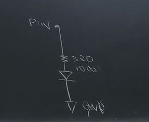
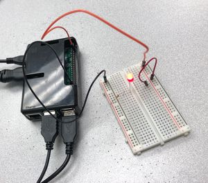
2. Isa: lit up LED light on Breadboard using Pi/programmed in Python (1.5 hours)
3. Amin: researched the best way to get GPS coordinates from pi and plot them on a map. Figured out that the best way to do so would be to write from the pi to a usb or sd card, and program a script that plots those coordinates on a map. (1.5 hours)
Retrieved from: https://www.instructables.com/id/Driving-an-ESCBrushless-Motor-Using-Raspberry-Pi/
Week 8: October 22nd - October 26th
GOALS:
- Locking mechanism: Figure out how it will work -- is there a way we can power it using Bluetooth?
- IDEA: Manual Clamp - similar to a boot design for a car
https://www.amazon.com/uxcell%C2%AE-Electric-Positions-Keylock-Switch/dp/B007QAJ2Q0
https://en.wikipedia.org/wiki/Wheel_clamp
https://www.autoanything.com/wheels-rims/what-are-wheel-locks
- Finish assembling Longboard (encase battery)
- Send GPS coordinates from Pi --> USB, write program that used these coordinates to map BOARDLOCK's location
1.) Amin: Made a python script that sends information to usb flash drive from raspberry pi (2 hrs)
2) Max: Designed a case for battery (1 hour)
- Dimensions:
130mm*155mm*65mm
3) Isa: sketch design and research logistics for locking clamp (1.5 hr)
- Using Pi's GPIO pins: lock/unlock wheels based on Bluetooth connection:
- Read INPUT pin that the switch is connected to, send OUTPUT to another pin -- powered by Pi
- If in close proximity of board -- assume strong Bluetooth connection -- switch ON (1) --> high voltage
- If far from board, assuming Bluetooth is disconnected, switch OFF (0) --> low voltage
Week 9: October 29th - November 2nd
GOALS:
1) Get the Pi and ESC to communicate for Locking Mechanism (handheld remote already controls the motor's speed)
- HOW? Wiring from the pins on the Pi to those on the ESC - Program 1 PMW input pin and 1 BEC output pin + Ground pin
M-M SERVO CONNECTER WIRING
- WHITE: PWM SIGNAL
- RED: +5V WIRE
- BLACK: GND
ESC pin abbreviations
GND = ground
RX = receive
TX = transmit
CLK = clock in
RST = reset
- Then, run a program in Python that will allow the Pi to control the motor through the ESC — allow it to move forward or not through different outputs of voltage
- This way, when BOARDLOCK is "Locked" = no voltage being passed to the motor, unable to move
2) Establish Bluetooth Connection with Pi, be able to give commands
- Bluetooth connection (ON vs OFF) --> Raspberry Pi (GPIO pins) --> ESC (powered by LiPo batteries) --> Motor
3) Get the GPS Chip and the Pi to communicate in order to display/map BOARDLOCK's coordinates in real time
- Manually connecting the chip to the Pi, connecting the Pi to a monitor, passing appropriate commands on Terminal
- Once this works, write a Python script that will parse useful data that we will use to map coordinates.
USEFUL TUTORIALS:
https://learn.adafruit.com/adafruit-ultimate-gps-on-the-raspberry-pi/setting-everything-up
https://www.youtube.com/watch?v=LVRXa8pX0Oc
https://www.piddlerintheroot.com/gps/
- CHALLENGES TO DISCUSS AT GROUP MEETING ON 10/31:
- Pi is extremely unreliable, connects to some monitors only, others say "No Signal"
- Limited by only having tested the GPS inside (Do we need an open space?)
- Pi Terminal does not recognize commands to give GPS chip, is not extracting information
- 3 specific input pins on the ESC belong to remote controller (Which can we use instead to connect to Pi?)
10/31: Amin and Isa: GPS chip and Pi are communicating! (2 hours)
USEFUL LINKS:
http://www.electronicwings.com/raspberry-pi/gps-module-interfacing-with-raspberry-pi
https://www.dfrobot.com/blog-772.html
http://www.rhydolabz.com/wiki/?p=9557
https://projects-raspberry.com/gps-module-for-raspberry-pi-tutorial/
FRIDAY 11/2:
- Write program to interpret raw data from Terminal, convert to useful information --> coordinates (latitude, longitude) in real time
PROJECT UPDATE:
Amin and Isa will pursue BOARDLOCK, make following modifications:
1. Using Amin's skateboard, will no longer be electric
2. Attach Pi, GPS Chip, and accelerometer onto underside of deck
Week 10: November 5th- November 9th
NEW OBJECTIVES
1. Interpret GPS data: Be able to locate BOARDLOCK's position in real time -- map coordinates onto Google Maps
CODE: https://docs.google.com/document/d/19fA9PHpmavBWK6MaLpt2g6CW3Tpq-B3MaB5QG7LGqPQ/edit?usp=sharing
https://gist.github.com/Lauszus/5785023
Program will read from/write to a text file
Amin & Isa (6 hours): gathered data from GPS chip on Pi terminal, parsed it, modified Python code to write it into a text file: latitude/longitude values
CODE: https://docs.google.com/document/d/1MuuRswUbI2rBpyrPwp7738kSjAMd38M18cf-FHi-cfo/edit?usp=sharing
2. Interpret Accelerometer data: Be able to see BOARDLOCK's speed, acceleration, distance
- Display on computer using USB Flash Drive
https://github.com/adafruit/Adafruit_Python_ADXL345/blob/master/setup.py
https://www.youtube.com/watch?v=NPTK0inTldw
3. Print box to hold Pi, GPS Chip, accelerometer
- Attach button to start/stop tracking -- program runs infinitely in background: has button been pressed? Should I start reading data?
- Light that indicates tracking on/off -- blinks if error
4. New Gantt Chart
- Program that parses GPS Chip data -- modify so it runs continuously and interacts with USB, button, LED light
- Program that visually produces table + map in Google maps from GPS Chip Data -- USER INTERFACE: displayed on Laptop
Week 11: November 12th- November 19th
Objectives: TEST EVERYTHING!!!!
- Accelerometer sends information to USB flash drive
Retrieved from https://tutorials-raspberrypi.com/measuring-rotation-and-acceleration-raspberry-pi/
- Program that parses accelerometer data/GPS coordinates to display onto Google Maps
- Route traveled, how fast you traveled @ specific points in your trip, highest acceleration achieved
- Put button w/ light on Raspberry Pi to instantiate data collection from GPS and accelerometer
- Light on => start collecting data (program ALWAYS running in background)
- Design & 3D print box encasing battery, Pi, GPS Chip, Accelerometer
- attach to underside of skateboard deck
USEFUL TUTORIALS
https://www.dimensionengineering.com/info/accelerometers
https://www.pubnub.com/blog-graphing-ultrasonic-sensor-realtime-data-raspberry-pi-soracom-pubnub/
CODE REPOSITORY: https://github.com/pubnub/pubnub-galileo-xyz
https://www.pubnub.com/blog/streaming-accelerometer-data-realtime-dashboard/
https://tutorials-raspberrypi.com/measuring-rotation-and-acceleration-raspberry-pi/


