Product: ABAQUS/Standard
S4 S4R S4R5 S8R S8R5 S9R5 STRI3 STRI65
SAX1 SAX2 SAXA1n SAXA2n
S8RT SAX2T
DS3 DS4 DS6 DS8 DSAX1 DSAX2
M3D3 M3D4 M3D4R M3D6 M3D8 M3D8R M3D9 M3D9R
For the three-dimensional shell and membrane elements (except the cylindrical membrane elements), the model consists of a tapered plate of length 100 and width 20. The plate is clamped at one end, and the thickness varies linearly across the plate from 3 at the clamped end to 1 at the free end. The first-order models consist of 10 elements along the length and two across the width; the second-order models consist of five elements along the length and one across the width.

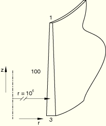
For the axisymmetric elements and the cylindrical membrane elements, the model consists of a tapered cylinder with a radius of 1 × 10⁶ and a length of 100. The cylinder is clamped at one end, and the thickness varies linearly along the length of the cylinder from 3 at the clamped end to 1 at the free end. The radius is chosen to be very large to ensure that the effects of circumferential stresses are negligible. The cylinder is meshed with ten first-order elements or five second-order elements.

For stress analysis: linear elastic, Young's modulus = 1000, Poisson's ratio = 0; for heat transfer: conductivity = 1.
Boundary conditions:
Clamped at the end with thickness 3.
Loading:
Shell bending model
Bending moment of 3 per unit length at the thin end of the shell.
Membrane tension model
In-plane force of 50 per unit length at the thin end of the membrane.
Axisymmetric membrane tension model
In-plane force of 50 per unit length at the thin end of the membrane.
Cylindrical membrane tension model
In-plane force of 50 per unit length at the thin end of the membrane. A beam type multi-point constraint is used to tie all nodes at the thin end of the membrane to a master node. The load is then applied to the master node. This problem is set up using the symmetric model generation capability (*SYMMETRIC MODEL GENERATION), with the corresponding axisymmetric problem as the base model.
Heat transfer shell model
Prescribed temperature = 0 at the thick end, prescribed temperature = 100 at the thin end.
Shell bending model
Tip displacement ![]() 20.0, tip rotation
20.0, tip rotation ![]() 0.8.
0.8.
Membrane tension model
Tip displacement ![]() 2.7465.
2.7465.
Axisymmetric membrane tension model
Tip displacement ![]() 2.7465.
2.7465.
Cylindrical membrane tension model
Tip displacement ![]() 2.7465.
2.7465.
Heat transfer shell model
Temperatures ![]() (20) = 13.03,
(20) = 13.03, ![]() (40) = 28.23,
(40) = 28.23, ![]() (60) = 46.50,
(60) = 46.50, ![]() (80) = 69.37.
(80) = 69.37.
All numerical solutions agree closely with the analytical solutions. The maximum error is about 1%. The *EL FILE, DIRECTIONS=YES option is used in input files es34dnsq.inp and em34sfsq.inp.
S3R elements.
S4 elements.
S4R elements.
S4R5 elements.
S8R elements.
S8R5 elements.
S9R5 elements.
STRI3 elements.
STRI65 elements.
SAX1 elements.
SAX2 elements.
SAXA11 elements.
SAXA12 elements.
SAXA13 elements.
SAXA14 elements.
SAXA21 elements.
SAXA22 elements.
SAXA23 elements.
SAXA24 elements.
S8RT elements.
SAX2T elements.
DS3 elements.
DS4 elements.
DS6 elements.
DS8 elements.
DSAX1 elements.
DSAX2 elements.
M3D3 elements.
M3D4 elements.
M3D4R elements.
M3D6 elements.
M3D8 elements.
M3D8R elements.
M3D9 elements.
M3D9R elements.
MAX1 elements.
MAX2 elements.
MGAX1 elements.
MGAX2 elements.
MCL6 elements.
MCL9 elements.