In some cases parts or part instances contain details such as very small faces and edges. These features can be important for the detailed machining and packaging design of the component; however, they may be redundant in the numerical analysis if they have little impact on the mechanics of the problem being studied. Indeed, these small details may unduly constrain the generation of the mesh, resulting in a poor mesh or a finer mesh density. In some circumstances small faces and edges can be significant if they occur in a region of interest where you need a fine mesh. However, in most cases the details add nothing to the analysis, and you want ABAQUS/CAE to ignore them during the mesh generation process and during the analysis.
The topology of the model is its composition from faces, edges, and vertices. The Virtual Topology toolset allows you to manipulate this topology and create a simplified form for the purpose of meshing. This simplified form is different from the real model and is called “virtual topology.” The faces and edges that result from the manipulation are said to be “virtual.” Similarly, parts and part instances that contain virtual faces and edges are said to be “virtual.”
The Virtual Topology toolset allows you to remove small details by combining a small face with an adjacent face or by combining a small edge with an adjacent edge. The faces or edges to be combined can be specified directly, or you can choose the edges and vertices to ignore.
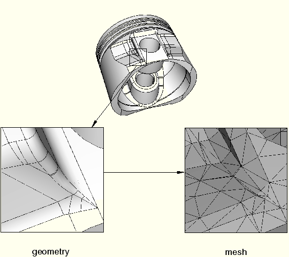
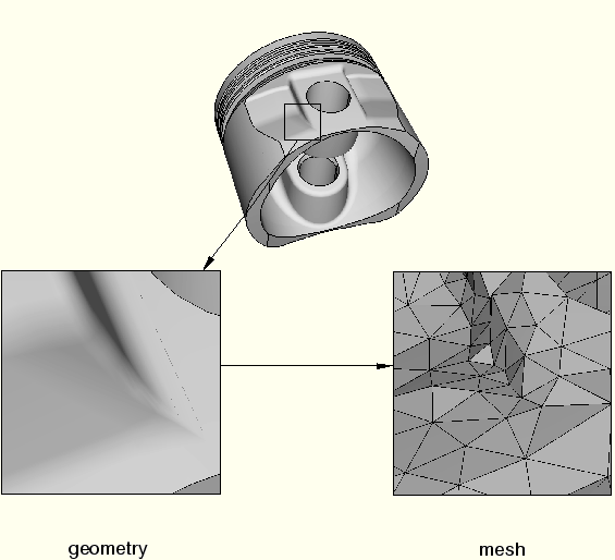
For example, Figure 49–1 shows a piston that has some small details where the blended surfaces intersect. These details result in a dense mesh that includes some sliver-shaped elements. You can use virtual topology to ignore the small details, resulting in the more uniform mesh of better quality that is illustrated in Figure 49–2.
Figure 49–2 Using virtual topology to ignore small details results in a more uniform mesh of better quality.
ABAQUS/CAE treats virtual topology in the same way that it treats standard geometry. For example, you can do the following:
Partition virtual topology.
Use the Repair toolset on virtual topology.
Use Part module tools on virtual topology, such as extrude, sweep, and blend.
Note: When you export a part containing virtual topology to an ACIS file, ABAQUS/CAE removes the virtual topology from the part that is exported.