
You can position a rectangular, cylindrical, or spherical datum coordinate system by selecting the following:
A point defining the origin.
A point on the X- or R-axis.
A point in the X–Y or R–![]() plane.
plane.
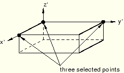
To create a datum coordinate system defined by three points:
From the main menu bar, select Tools![]() Datum.
Datum.
The Create Datum dialog box appears. The dialog box outlines the types of datum geometry you can create.
ABAQUS/CAE displays prompts in the prompt area to guide you through the procedure.
Tip:
You can also create a datum coordinate system using the ![]() tool, located in the module toolbox. For a diagram of the datum tools in the toolbox, see “Using the Datum toolset,” Section 40.2.
tool, located in the module toolbox. For a diagram of the datum tools in the toolbox, see “Using the Datum toolset,” Section 40.2.
From the list of types at the top of the dialog box, choose CSYS.
The Method list indicates the methods you can use to create a datum coordinate system.
From the Method list, select 3 points and click OK.
ABAQUS/CAE displays the Create Datum CSYS dialog box.
From the dialog box, enter the name of the datum coordinate system.
To help keep track of your datum coordinate systems, ABAQUS/CAE displays its name in the Model Tree. In addition, you can use the Model Tree to rename the datum coordinate system.
From the dialog box, select one of the following datum coordinate systems:
Rectangular: The X-, Y-, and Z-axes are aligned with the 1-, 2-, and 3-global axes, respectively.
Cylindrical: The R-, ![]() -, and Z-axes are aligned with the 1-, 2-, and 3-global axes, respectively.
-, and Z-axes are aligned with the 1-, 2-, and 3-global axes, respectively.
Spherical: The R-, ![]() -, and
-, and ![]() -axes are aligned with the 1-, 2-, and 3-global axes, respectively.
-axes are aligned with the 1-, 2-, and 3-global axes, respectively.
From the Create Datum CSYS dialog box, click Continue.
ABAQUS/CAE displays a default datum coordinate system. The origin of the datum coordinate system is located at the origin of the part or assembly. In addition, the axes of the default datum coordinate system are aligned with the coordinate system of the part or assembly.
If you want to accept the default datum coordinate system, click Create Datum from the prompt area.
ABAQUS/CAE creates the datum coordinate system.
To create a datum coordinate system at a different location or with a different orientation, do the following:
From the part or assembly in the current viewport, select a point that will define the origin of the datum coordinate system or enter the coordinates of the origin.
ABAQUS/CAE displays a temporary datum coordinate system at the selected point. The axes of the datum coordinate system are aligned with the axes of the global coordinate system.
From the prompt area, click Create Datum to accept the default orientation of the temporary datum coordinate system or select (or enter the coordinates of) a point that will lie on the X- or R-axis.
ABAQUS/CAE recalculates the orientation of the temporary datum coordinate system.
From the prompt area, click Create Datum to accept the new orientation of the temporary datum coordinate system or select (or enter the coordinates of) a point that will lie on the X–Y or R–![]() plane.
plane.
ABAQUS/CAE creates the datum coordinate system. You cannot move or rotate a datum coordinate system.
