When you choose Plane from the Create Datum dialog box, the Method list displays the following methods for creating a datum plane:
![]() Offset from principal plane
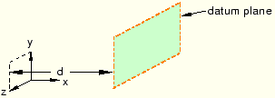
Offset from principal plane
Select one of the three principal planes; and provide the location of the datum plane in the form of an offset from the selected plane, as shown in Figure 40–22. A positive value indicates an offset in the positive direction along the axis normal to the selected plane; for example, along the X-axis normal to the Y–Z plane. For detailed instructions, see “Creating a datum plane offset from a principal plane,” Section 40.8.1.
![]() Offset from plane
Offset from plane
Select any plane on the model; and provide the location of the datum plane by specifying the direction of the normal and an offset from the selected plane along the normal, as shown in Figure 40–23. You can specify the offset by entering a value or selecting a point. For detailed instructions, see “Creating a datum plane at an offset from a selected plane,” Section 40.8.2.
![]() 3 points
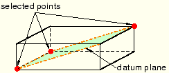
3 points
Select three points through which the datum plane must pass, as shown in Figure 40–24. For detailed instructions, see “Creating a datum plane passing through three points,” Section 40.8.3.
![]() Line and point
Line and point
Select an edge and a point through which the datum plane must pass, as shown in Figure 40–25. For detailed instructions, see “Creating a datum plane through a line and a point,” Section 40.8.4.
![]() Point and normal
Point and normal
Select a point and an edge; the datum plane passes through the point and is normal to the selected edge, as shown in Figure 40–26. For detailed instructions, see “Creating a datum plane passing through a point and normal to an edge,” Section 40.8.5.
![]() Midway between 2 points
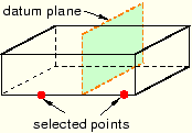
Midway between 2 points
Select two points. ABAQUS/CAE creates a datum plane midway between the two selected points and normal to the line connecting them, as shown in Figure 40–27. For detailed instructions, see “Create a datum plane midway between two points and normal to the line connecting the two points,” Section 40.8.6.
![]() Rotate from plane
Rotate from plane
Select a face and an axis of rotation, and specify the angle through which the face will be rotated. ABAQUS/CAE creates a datum plane by rotating the face about the axis through the specified angle, as shown in Figure 40–28. For detailed instructions, see “Creating a datum plane by rotating an existing face through a specified angle,” Section 40.8.7.