The common and superimposed plot options determine which model edges appear in all plot states. When you specify that only feature edges are to be visible, ABAQUS/CAE determines which edges meet this criteria. Feature edges lie between elements having normals that differ by more than the “feature angle.” You can customize the feature angle. Larger angles will reduce the number of feature edges; conversely, smaller angles will cause more edges to be visible. The default is 30°. The setting of the feature angle applies to all plot states. However, all segment edges are drawn for analytical rigid surfaces regardless of the feature angle setting.
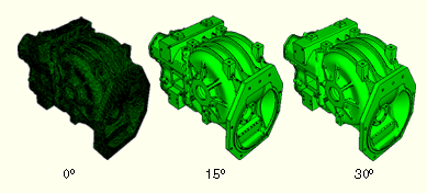
In Figure 36–3 the plot on the left shows feature edges when the feature angle is set to 0°, the plot in the middle shows feature edges on the same model but with the feature angle set to 15°, and the plot on the right shows the model with the feature angle set to 30°.
To customize the feature angle:
Locate the Feature Angle options.
From the main menu bar, select View![]() ODB Display Options. Click the General tab in the dialog box that appears. The Feature Angle options are at the bottom of the General page.
ODB Display Options. Click the General tab in the dialog box that appears. The Feature Angle options are at the bottom of the General page.
Drag the Feature Angle slider to the desired feature angle.
Click Apply to implement your changes.
Feature edges for all plot states change to reflect your feature angle specification, which is saved for the duration of the session.