A path is a line you define by specifying a series of points or line segments through your model. The points can be nodes or coordinate locations; the line segments can be element edges or lines joining the ends of element edges. Paths can cross more than one part instance. ABAQUS/CAE offers four distinct types of paths:
Node list
The points making up the path consist of nodal locations only. You specify the points using node labels and node label ranges. A node label is a persistent means of referring to a given node; that is, node labels do not change as your model deforms. Because of this, the node labels that comprise a node list path are equally applicable to the undeformed or the deformed model shape. However, node labels are part instance-specific. In other words, you can have the same node label for multiple part instances; therefore, you must specify to which part instance you are referring when you use node labels. For more information, see “Creating or editing a node list path,” Section 31.2.1.
Point list
The points making up the path consist of coordinate locations within your model. These locations may or may not coincide with nodal locations. Point list coordinates remain fixed in space and are independent of your model. For example, coordinates that coincide with a nodal location on the undeformed shape may not coincide with any location on the deformed shape. By the same logic, point list coordinates are independent of specific part instances. For more information, see “Creating or editing a point list path,” Section 31.2.2.
Edge list
The points making up the path consist of edges that connect nodes within your model. You specify the edges by selecting individual element edges from the viewport or by selecting the starting edge and direction and allowing ABAQUS/CAE to automatically complete the path to the end of the feature edge or to an endpoint that you select. Edges are defined by the elements in the model. Because of this, the edges that comprise an edge list path are equally applicable to the undeformed or the deformed model shape. However, element labels are part instance-specific. In other words, you can have the same element label for multiple part instances; therefore, you must specify to which part instance you are referring when you use edges. For more information, see “Creating or editing an edge list path,” Section 31.2.3.
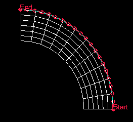
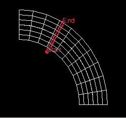
Circular
The points making up the path consist of coordinate locations within your model. You can create two types of circular paths in ABAQUS/CAE: circumferential and radial. A circumferential path lies along the edge of a circle or an arc; a radial path lies along a radius. You specify either type of path by selecting coordinates that define a circle or circular arc and then defining the starting point, ending point, and number of points along the path. Once you have defined the original circle or arc, you can select a new radius length to create any path that shares the same center point as the original. You can use circumferential paths to obtain cross-sectional results in a curved portion of a model, as shown in Figure 31–1. You can use radial paths to obtain results spanning from the inner to the outer face of a curve, as shown in Figure 31–2; radial paths are ideal for use in stress linearization (for more information on stress linearization, see Chapter 32, “Calculating linearized stresses”). You can select coordinates by picking nodes from the viewport or by entering values in the prompt area; in either case, the coordinates remain fixed in space and are independent of your model. For example, coordinates that coincide with a nodal location on the undeformed shape may not coincide with any location on the deformed shape. By the same logic, circular path coordinate definitions are independent of specific part instances. For more information, see “Creating or editing a circular path,” Section 31.2.4.
After you create a path, you can select Tools![]() Path from the main menu bar to edit, copy, rename, delete, or plot it. Plotting the path itself is a means to verify visually that you have specified the intended line; to view results along the path, you must form X–Y data pairs and produce an X–Y plot. For more information on managing paths, see “Managing objects using manager dialog boxes,” Section 3.4.9; for more information on producing an X–Y plot of path data, see “Obtaining X–Y data along a path,” Section 31.3.
Path from the main menu bar to edit, copy, rename, delete, or plot it. Plotting the path itself is a means to verify visually that you have specified the intended line; to view results along the path, you must form X–Y data pairs and produce an X–Y plot. For more information on managing paths, see “Managing objects using manager dialog boxes,” Section 3.4.9; for more information on producing an X–Y plot of path data, see “Obtaining X–Y data along a path,” Section 31.3.