A display body is a part instance that will be used for display only. The part instance can be an instance of an ABAQUS native part, or it can be an instance of an orphan mesh. You do not have to mesh the part, and the part is not included in the analysis; however, when you view the results of the analysis, the Visualization module displays the part along with the rest of your model. In effect, a display body provides a more realistic view of your model in the Visualization module without the computational expense of including the part instance in the analysis. A display body behaves like a rigid part and does not deform. You cannot apply prescribed conditions, such as constraints, loads, or boundary conditions, to a display body.
You can associate the motion of a display body with selected control points (one point or three points), or you can specify that the display body remain fixed during the analysis. If the display body follows a single point, the display body will translate and rotate based on the translations and rotations of the single point. If the display body follows three points, the display body will translate and rotate based on the translation of the three points. For more information, see “Display body definition,” Section 2.8.1 of the ABAQUS Analysis User's Manual.
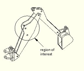
For example, Figure 21–14 shows a backhoe arm modeled with connectors.
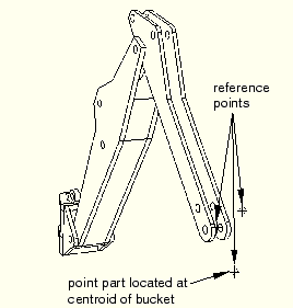
The region of interest is the main arm of the backhoe. The bucket interacts with the rest of the backhoe model only through the connectors and the mass and inertia of the bucket. As a result, the bucket can be modeled as a display body.You create a display body by applying a display body constraint to a part instance. For the backhoe arm model you would first create the bucket part instance in the Part module. In addition, you would create a point part and position it at the centroid of the bucket in the assembly, as shown in Figure 21–15 (see “Point parts,” Section 11.8.2); a reference point is automatically created for the point part.
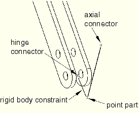
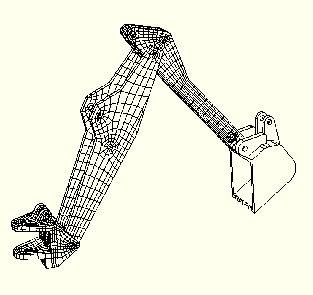
The other two reference points in the assembly serve as endpoints for a HINGE and an AXIAL connector; see “Modeling connectors,” Section 21.3, for more information on connectors. In the Interaction module you would create a rigid body constraint to constrain the endpoints and the point part to move as a single rigid entity, as shown in Figure 21–16; see “Defining rigid body constraints,” Section 15.14.2. In addition, you would create a display body constraint to constrain the bucket part instance to the point part; see “Defining display body constraints,” Section 15.14.3.You do not have to mesh the bucket part instance, and it is not included in the analysis of the backhoe model. However, the bucket still appears when you view the results of the analysis in the Visualization module, as shown in Figure 21–17.
Display bodies are useful if your model contains a part that cannot be meshed and need not be analyzed. In general, an imported part that has invalid geometry cannot be used by ABAQUS/CAE. However, if you apply a display body constraint to the part, you can continue to use the part in your model, although the part will not be included in the analysis. For more information, see “What is a valid and precise part?,” Section 10.2.1.