You use continuum shell elements to model shell-like solids with greater accuracy than conventional shell elements, as described in “Shell elements: overview,” Section 23.6.1 of the ABAQUS Analysis User's Manual. In addition, although you model a continuum shell with hexahedral- or wedge-shaped elements, the element formulations are still more computationally efficient than solid continuum elements.
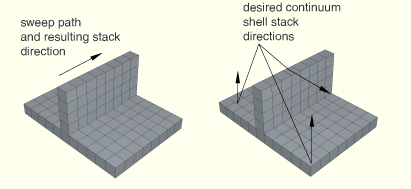
When you are generating elements that will be assigned to continuum shell elements, the elements in the mesh must be oriented consistently. This restriction imposes limitations on how the mesh can be generated. For example, Figure 21–10 shows a swept mesh generated in the direction of the sweep path. The generated elements are stacked in the direction of the sweep path; however, if you plan to use continuum shell elements, the elements should be stacked through their thickness.
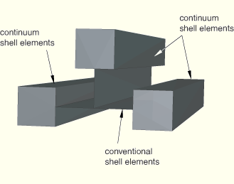
In some cases, you can partition the model and change the direction of the sweep path to obtain the correct orientation. Alternatively, you can query the model to determine the stack orientation and use the Edit Mesh toolset to reorient the stack orientation of an orphan mesh. For more information, see “Querying your mesh,” Section 17.6.2, and “Orienting the stack direction,” Section 41.6.4. However, in some cases you may not be able to orient all of the elements consistently. If you cannot maintain consistent element orientation throughout the mesh, you should tie the elements at the interface where the orientation is inconsistent.Alternatively, you can use conventional solid or shell elements to connect the continuum shell elements at the interface where the orientation is inconsistent. Figure 21–11 illustrates how you can model a branch region containing conventional shells and continuum shells using solid-to-shell tied contact. You can use this approach for shell elements combined with either solid or continuum shell elements.
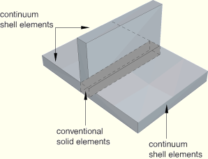
Figure 21–12 illustrates how you can model a branch region using a combination of solid elements and continuum shell elements.To avoid issues with the element stack orientation, you may find it more convenient to generate continuum shell elements using the offset meshing tool in the Edit Mesh toolset. However, you can create offset meshes only with orphan mesh parts, and you lose the functionality that associates the mesh with an ABAQUS/CAE native part; for example, the ability to modify the original part and quickly regenerate the mesh.
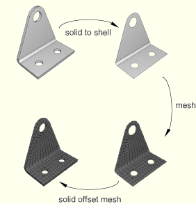
You should use the following strategy to mesh a part with continuum shell elements using the offset meshing technique:
Convert the solid part to a shell using the From solid shell tool in the Part module.
Isolate a collection of faces that represents an idealized shell of the part using the Remove faces tool in the Repair toolset.
Mesh the simplified model with shell elements and create an orphan mesh part.
Use the orphan mesh part to generate an offset mesh of solid hexahedral or wedge elements. The elements will be oriented through the thickness of the part, and you can verify this with the Query toolset.
Use the element type assignment tool in the Mesh module to assign continuum shell elements to the part.