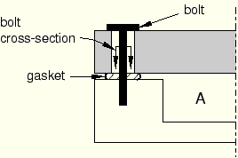
Bolt loads model tightening forces or length adjustments in bolts or fasteners. For example, Figure 21–2 shows a container (A) that is sealed by tightening the bolts that hold the lid, which places the gasket under pressure.
You can model the tension in the tightened bolts by applying a bolt load to each one in the first step of the analysis. You define the load in terms of either a concentrated force or a prescribed change in length, and you apply the load across a bolt cross-section surface that you specify. In later steps you can modify the load to prevent further length changes so that the bolt acts as a standard, deformable component responding to other loadings on the assembly.When you create a bolt load, you must specify the following:
A surface that defines the bolt cross-section
ABAQUS/CAE applies the bolt load across the cross-section surface that you specify. The surface that defines the bolt cross-section must cut through the bolt geometry. ABAQUS/CAE creates an “internal” surface at that location.
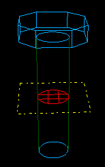
If you are working with bolt part instances made from native or imported geometry, it is usually necessary to partition the bolt at the location where you want the cross-section to be defined. For example, a partition is selected as the bolt cross-section in Figure 21–3.
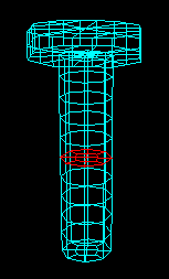
If you are working with an orphan mesh part, you must specify the cross-section surface by selecting element faces. For example, element faces define a cross-section surface for the orphan mesh shown in Figure 21–4. For more information on selecting surfaces, see Chapter 6, “Selecting objects within the viewport.” For detailed information on selecting surfaces on wire part instances, see “Specifying a particular side or end of a region,” Section 48.2.5.Note: You can apply bolt loads only to three-dimensional solid, two-dimensional solid, and three-dimensional wire part instances. Bolt loads on two-dimensional and axisymmetric wire part instances are unsupported.
A bolt axis
If you are defining a bolt load on a solid region, you must select a datum axis or one of the axes of a datum coordinate system that indicates the bolt axis direction (it need not be normal to the cross-section). If you are defining a bolt load on a wire region, the bolt axis direction is always assumed to be the direction of the tangent to the wire at the bolt cross-section.
ABAQUS/CAE uses both the cross-section surface that you specify and the bolt axis to define the pre-tension section data and the pre-tension reference node used by ABAQUS/Standard. (See “Prescribed assembly loads,” Section 27.5.1 of the ABAQUS Analysis User's Manual, for more information.)
A method for applying the loading
When you create a bolt load, you must choose one of the following loading methods:
Apply a force to the bolt. This method models tightening the bolt so that it carries a specified load.
Adjust the bolt length. This method models tightening the bolt until its free length has changed by the specified value.
Fix the bolt at its current length. This method is available only if you have already created the load in the first analysis step and are now editing it in a subsequent analysis step. This method allows the bolt length to remain unchanged so that the force in the bolt can change according to the response of the model.
A magnitude for the chosen method
If you are applying a force to the bolt, you must enter the force magnitude. If you are adjusting the bolt length, you must enter the length change.
You can create a bolt load only in the first analysis step, but you can modify the loading method or the magnitude of the load in subsequent steps. For example, you can apply a specific tension in the first step and then change the method in the second step to fix the bolt length.
For detailed information on creating a bolt load, see “Creating and editing bolt loads,” Section 21.2.2.