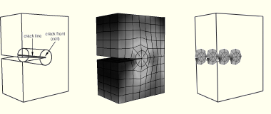
The first step in the procedure to configure a contour integral is to define the crack front by selecting entities from the assembly. The crack front is the forward part of the crack. ABAQUS uses the crack front to compute the first contour integral using all of the elements inside the crack front and one layer of elements outside the crack front. You can request output for more than one contour integral, in which case ABAQUS/CAE adds a single layer of elements to the group of elements that were used to calculate the previous contour integral. Figure 20–2 illustrates how ABAQUS/CAE computes successive contour integrals for a two-dimensional model by adding layers of elements.
If your part is three-dimensional, ABAQUS computes contour integrals at each node along the crack line, as shown in Figure 20–3. For more information, see “Defining the crack front” in “Contour integral evaluation,” Section 11.4.2 of the ABAQUS Analysis User's Manual.
The entities from which you can select depend on whether the part instance is an ABAQUS native part or an orphan mesh part and on the modeling space of the part.
ABAQUS native part instance
When you are defining the crack front on an ABAQUS/CAE native part, the entities that you can select depend on the modeling space of the part.
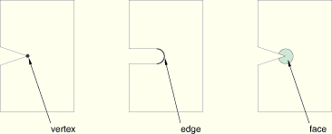
Two-dimensional part instance
If you are defining the crack front on a two-dimensional ABAQUS/CAE native part, you can select the following:
A single vertex
Connected edges
Conected faces
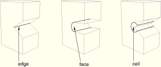
Three-dimensional part instance
If you are defining the crack front on a three-dimensional ABAQUS/CAE native part, you can select the following:
Connected edges
Connected faces
Connected cells
Orphan mesh part instance
When you are defining the crack front on an orphan mesh part, you can select the elements or element edges or faces that define the crack front. Alternatively, you can select the nodes from the corresponding region. When you are defining the crack front on an orphan mesh part, the entities that you can select depend on the modeling space of the part.
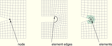
Two-dimensional part instance
If you are defining the crack front on a two-dimensional orphan mesh part, you can select the following:
A single node
Connected element edges
Connected elements
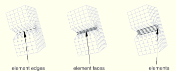
Three-dimensional part instance
If you are defining the crack front on a three-dimensional orphan mesh part, you can select the following:
Connected element edges
Connected element faces
Connected elements