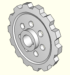
You can copy objects in your sketch and create a pattern of copied objects; for example, Figure 19–19 illustrates radial patterns of gear teeth and holes on a solid part.
You can choose either of the following methods to define the pattern:Linear pattern
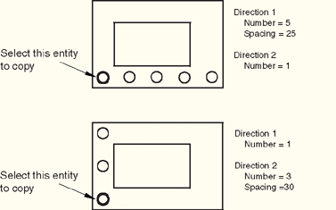
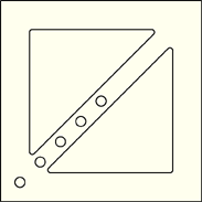
A linear pattern positions copies of selected objects along a direction; for example, the X-direction. You can specify the number of copies and the spacing between the copies; and you can choose to position the copies in a positive direction or a negative direction. In addition, you can change the orientation of the linear pattern. Figure 19–20 shows how you can create different linear patterns in a single direction.
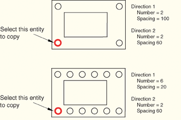
You can create a matrix of copied objects by creating copies in a second direction; for example, the Y-direction. The options are the same as for the first direction; you can control the number of copies, the direction, and the angle. Figure 19–21 shows how you can create different linear patterns in two directions.
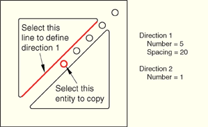
By default, the first direction is the X-axis and the second direction is the Y-axis. However, you can change the orientation of the first direction or the second direction by selecting a line from the sketch that represents the new orientation. Figure 19–22 shows a linear pattern oriented along a selected line.
By default, ABAQUS/CAE creates the pattern in a positive direction; however, you can reverse the direction. For example, Figure 19–23 shows the same linear pattern as in Figure 19–22 but with the direction reversed. For detailed instructions on creating linear patterns, see “Creating linear patterns of objects,” Section 19.18.1.Radial pattern
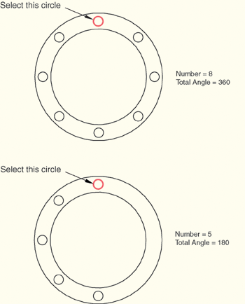
A radial pattern positions copies of selected objects in a circular pattern. You can specify the number of copies, and you can specify the angle between the first and last copy, where a positive angle corresponds to a counterclockwise direction. In addition, you can select a point from the sketch that defines the center point of the circular pattern. Figure 19–24 shows how you can create different radial patterns.
For detailed instructions on creating radial patterns, see “Creating radial patterns of objects,” Section 19.18.2.Several methods are also available for creating individual copies of sketch objects. These methods are discussed in “Modifying or copying objects by selecting edges,” Section 19.8.3.