
You can define a nonuniform distribution of elements along a particular edge by selecting Seed![]() Edge Biased from the main menu bar. You must provide a bias value, which is defined as the ratio of the size of the coarsest element to the size of the finest element along an edge.
Edge Biased from the main menu bar. You must provide a bias value, which is defined as the ratio of the size of the coarsest element to the size of the finest element along an edge.
For example, the bias value for the seeded edges shown below is five; the largest element on the edge will be five times larger than the smallest element on the edge.
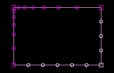
All the edge seeding tools generate edge seeds, which are displayed in magenta. Edge seeds override any part or instance seeds you have specified.
To prescribe biased seeding along an edge:
From the main menu bar, select Seed![]() Edge Biased.
Edge Biased.
ABAQUS/CAE displays prompts in the prompt area to guide you through the procedure.
Tip:
You can also click the ![]() tool, located with the seed tools in the Mesh module toolbox. (For more information, see “Using the Mesh module toolbox,” Section 17.13.)
tool, located with the seed tools in the Mesh module toolbox. (For more information, see “Using the Mesh module toolbox,” Section 17.13.)
Select the edges you want to seed. As you select each edge, click near the end where you want the mesh to be denser.
For more information on selecting objects, see Chapter 6, “Selecting objects within the viewport.”
Click mouse button 2 to commit your selections.
An arrow appears on each selected edge indicating the direction in which the element size will decrease.
In the text box in the prompt area, type the bias ratio to be used along the selected edges. The bias ratio must be greater than or equal to one and less than or equal to 1.0E6.
Press [Enter] or mouse button 2 to commit your bias setting.
In the text field in the prompt area, type the desired number of elements to be created along the selected edges.
If desired, change the default seed constraints by clicking the Constraints button in the prompt area and responding to the dialog box that appears. See “Applying constraints to edge seeds,” Section 17.14.5, for further information on setting seed constraints.
Press [Enter] or mouse button 2 to accept the element number and constraint settings.
Magenta seeds appear on the selected edges of the part instance.
To seed additional edges, repeat this procedure from Step 2.
To exit the edge seeding procedure, press [Enter] or click mouse button 2.
