ABAQUS/CAE assigns a default meshing technique to each region depending on its geometry and topology. However, sometimes the default meshing techniques applied to adjacent regions of a three-dimensional part or part instance are not compatible, and ABAQUS/CAE cannot generate a compatible mesh.
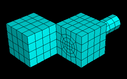
For example, ABAQUS/CAE cannot generate a compatible mesh over the entire part instance in Figure 17–90 using the default meshing techniques because the nodes from the structured mesh on the left cannot be merged with the nodes of the swept mesh on the right. (The cube on the right side of the part instance is a swept region because it is joined to the cylinder, which is also a swept region.)
The mismatch that would occur between the nodes of the structured region and the nodes of the swept region is obvious if you mesh the two regions separately, as shown in Figure 17–91.If you initiate the meshing procedure and ABAQUS/CAE cannot generate a compatible mesh using the default meshing techniques, ABAQUS/CAE attempts to replace the default meshing techniques with new meshing techniques. These new techniques are determined not only by the region's geometry and topology but also by the characteristics of neighboring regions in the part or part instance. ABAQUS/CAE evaluates the interfaces between regions and tries to minimize the number of incompatible interfaces.
For example, the default meshing technique for the cube on the left side of the part instance in Figure 17–90 is structured, and the resulting incompatible mesh is shown in Figure 17–91. However, this cube can also be meshed using the swept meshing technique. Therefore, ABAQUS/CAE changes the meshing technique assigned to this region from structured to swept, and a compatible mesh is generated over the whole part instance. (The element shapes assigned to a region remain unchanged when ABAQUS/CAE changes the meshing technique assigned to the region.)
When you initiate the meshing procedure for a three-dimensional part or part instance, ABAQUS/CAE determines if a compatible mesh can be generated using the default techniques assigned to each region. If a compatible mesh is possible, meshing proceeds. If a compatible mesh cannot be generated using the default techniques, ABAQUS/CAE checks to see if it can replace the default meshing techniques with different techniques that will allow a compatible mesh to be generated.
If different techniques will allow a compatible mesh, ABAQUS/CAE highlights the incompatible interfaces and prompts you to select one of the following options:
Cancel the meshing procedure.
Allow ABAQUS/CAE to replace the default techniques as necessary and generate a compatible mesh.
Allow ABAQUS/CAE to use the default meshing techniques and automatically generate tie constraints across the incompatible interfaces. ABAQUS/CAE automatically chooses one side of the interface as the slave surface and the other as the master surface for the automatically generated tie constraint but creates common (merged) nodes on the perimeter of the incompatible interface. The nodes on the slave surface are constrained to have the same value of displacement, temperature, pore pressure, or electrical potential as the point on the master surface to which they are tied. ABAQUS/CAE generally selects the surface with the finer mesh to be the slave surface. The computation for the depth of the slave node adjustment zone for the tie constraint is based on the bounding dimensions of the interfacing regions. (For more information on tie constraints, see “Mesh tie constraints,” Section 28.3.1 of the ABAQUS Analysis User's Manual.)
If different techniques will still not allow a compatible mesh, ABAQUS/CAE highlights the incompatible interfaces and prompts you to select one of the following options:
Cancel the meshing procedure.
Automatically generate tied surface interactions across the incompatible interfaces, as described above.
Partition as necessary to generate a compatible mesh.
Use the free meshing technique to mesh the entire part or part instance.
In general, the following restrictions apply to generating a compatible mesh on a three-dimensional solid part or part instance:
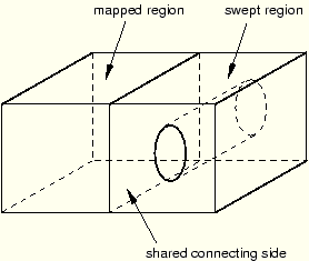
A swept region cannot share its target side with a structured region. However, it can share a source side or a connecting side with a structured region, as shown in Figure 17–92.
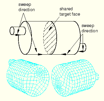
In some situations ABAQUS/CAE cannot mesh a part or part instance that contains multiple regions that have all been assigned the swept meshing technique. For example, ABAQUS/CAE cannot sweep a mesh along the part instance shown in Figure 17–93 because a compatible mesh cannot be generated on the shared target face.
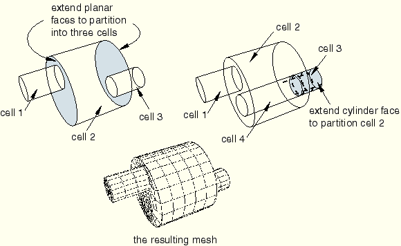
However, Figure 17–94 shows how you can use partitions to produce a mesh that incorporates four swept regions.Different regions of the same part or part instance can be meshed with hexahedral and tetrahedral elements as shown in Figure 17–95.
You can use the hexahedral elements where accuracy is important, such as adjacent to contact surfaces or in areas of special interest that require a fine mesh. You can use tetrahedral elements in other regions, and ABAQUS/CAE creates tied surfaces where the regions connect. When you mesh one region, ABAQUS/CAE does not adjust an existing mesh on adjacent regions.