A two-dimensional region can be meshed using the structured meshing technique if it has the following characteristics:
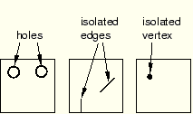
The region has no holes, isolated edges, or isolated vertices. Figure 17–44 shows regions that cannot be structured meshed.
The region is bounded by three to five logical sides, where each side is a connected set of edges.
In general, structured meshing gives you the most control over the mesh that ABAQUS/CAE generates. If you are meshing a four-sided region with all quadrilateral elements, the total number of element edges around the boundary must be even. For three- and five-sided regions, the constraint equations are more complex. ABAQUS/CAE respects seed distribution wherever possible when generating a structured mesh. (Seed distribution describes the spacing of the seeds, not necessarily the number of seeds. For example, are the seeds evenly spaced along an edge or more concentrated at one end?) However, meshes must be compatible across regions, and ABAQUS/CAE may adjust the nodes of a mesh region that is adjacent to a region that was meshed using the free meshing technique. As a result, the element nodes may not match the seeds exactly.
Figure 17–45 shows the seeds on the edges of a four-sided region and the effect of different mesh controls. The mesh control effects are as follows:
In four-sided regions the quadrilateral-dominated structured mesh matches the seeding exactly. There are an odd number of elements around the boundary, and ABAQUS/CAE inserts a single triangle into the mesh. (In contrast, when you mesh a three- or a five-sided region with structured quadrilateral-dominated elements, ABAQUS/CAE does not insert any triangles. The resulting mesh uses all quadrilateral elements; however, the resulting mesh may not match the mesh seeding exactly.)
The two quadrilateral structured meshes do not match the seeding. This is even more apparent when you choose to minimize the mesh transition.
The triangular structured mesh also does not match the seeding. ABAQUS/CAE creates the triangular mesh by splitting the diagonals of the quadrilateral structured mesh with minimized mesh transition.
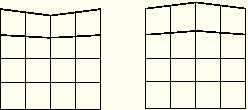
ABAQUS/CAE combines edges into a logical side automatically if the edges subtend a shallow angle. For example, each region in Figure 17–46 has five edges. However, since the top two edges in each region subtend a shallow angle, ABAQUS/CAE considers these two edges to be one logical side. Therefore, the mesh pattern for four-sided regions is applied to these regions. If the region contains virtual topology, you can mesh the region using the structured meshing technique only if the region is bounded by four sides. You cannot use structured meshing to mesh three- or five-sided regions that contain virtual topology.
You can use the Redefine Region Corners button in the Mesh Controls dialog box to combine edges yourself, regardless of the angle they subtend. (To display the Mesh Controls dialog box, select Mesh![]() Controls from the main menu bar.) This technique allows you to control which structured mesh pattern is applied to the two-dimensional region. (This technique is not available for three-dimensional regions.) For more information, see “Redefining region corners,” Section 17.16.4.
Controls from the main menu bar.) This technique allows you to control which structured mesh pattern is applied to the two-dimensional region. (This technique is not available for three-dimensional regions.) For more information, see “Redefining region corners,” Section 17.16.4.
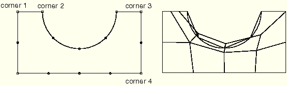
The region that you plan to mesh with structured quadrilateral elements must be well shaped; otherwise, ABAQUS/CAE may create invalid elements as shown in Figure 17–47.
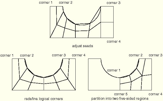
If the mesh contains invalid elements, you can use several techniques to correct the mesh:Adjust the position of the mesh seeds.
Redefine the region corners.
Partition the face into smaller, better shaped regions.