Select Instance![]() Merge/Cut from the main menu bar to merge multiple instances of meshed parts. Although merging meshed part instances is similar to merging native part instances, you cannot cut instances of meshed parts.
Merge/Cut from the main menu bar to merge multiple instances of meshed parts. Although merging meshed part instances is similar to merging native part instances, you cannot cut instances of meshed parts.
The meshed part instances can be:
Orphan mesh part instances
Meshed dependent part instances (where you have already meshed the original part in the Mesh module).
Meshed independent part instances (where you have already meshed the part instance in the Mesh module).
Any combination of these three.
You can merge multiple meshed part instances. Merging meshed part instances is similar to merging unmeshed part instances in that the operation creates a new part instance and a new part. Similarly, you can choose to suppress or retain the original meshed part instances. If you have already meshed parts that you created with ABAQUS/CAE, you can choose between merging their geometry or merging their meshes. If you choose to merge their geometry, ABAQUS/CAE creates a new part instance and a new part and the original meshes are deleted in the process. If you choose to merge their meshes, ABAQUS/CAE creates a new orphan mesh part instance and a new orphan mesh part and the original meshes are merged into a single mesh. The discussion in the remainder of this section assumes that you chose to merge the meshes of the selected instances.
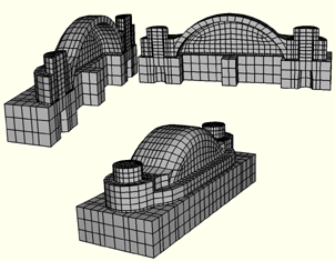
Figure 13–20 shows how you can position two instances of meshed parts along a common face and merge them into a single meshed part instance.
If you select instances that contain sets, ABAQUS/CAE updates your sets during the merge operation.You can specify the Node merging tolerance, which is the maximum distance between nodes that will be merged. ABAQUS/CAE creates a compatible mesh by deleting nodes that are closer than the specified distance and replacing them with a single new node. The location of the new node is the average position of the deleted nodes. If the value that you entered for the Node merging tolerance is too large, ABAQUS/CAE may detect duplicate nodes from the same element. ABAQUS/CAE will not merge nodes from the same element. However, the large tolerance can result in a distorted mesh, and ABAQUS/CAE asks if you want to continue or end the merging procedure. If no nodes are closer than the specified distance, ABAQUS/CAE asks if you want to cancel the procedure or create a single instance from the selected instances.
When you merge meshed part instances that intersect, you can choose whether to create duplicate elements as well as duplicate nodes. A duplicate element has the same connectivity as another element. By default, ABAQUS/CAE deletes duplicate elements, and in most cases you should accept the default behavior. However, you must retain duplicate elements if you want to model a material with a combination of material properties that are not supported by ABAQUS, as described in the discussion of stability in “No compression or no tension,” Section 17.2.2 of the ABAQUS Analysis User's Manual.
You can choose between the following methods for merging the nodes:
Boundary only
By default, ABAQUS/CAE merges the meshed part instances only along their boundaries. As a result, ABAQUS/CAE does not check for duplicate nodes in the interior of the parts, which speeds up the merging process. You should retain this default setting if the part instances intersect at only a common face.
All
If the part instances overlap, you may want to merge all the nodes in the selected part instances.
None
Alternatively, you can choose to merge none of the nodes, in which case ABAQUS/CAE merges the part instances into a single instance but retains all the original nodes.
In many cases you will be merging part instances that do not intersect but share a common face; for example, the two part instances shown in Figure 13–20. If desired, you can use the Part Copy dialog box to create a mirror image of a part about one of the three principal planes. For more information, see “Copying a part,” Section 11.5.
You can also merge selected nodes of an orphan mesh part using the Edit Mesh toolset; for more information, see “Manipulating nodes,” Section 41.1.1.
Although the resulting merged mesh may appear acceptable in the viewport, the mesh may contain small gaps between a node and an element face that are not readily apparent. The mesh may also contain merged faces that have an incompatible mesh pattern. You can use the Mesh gaps/intersections tool in the Query toolset to check for small gaps and incompatible faces. For more information, see “Obtaining general information about the model,” Section 45.2.2.