You can create multiple copies of a selected part instance in either a linear or radial pattern. You can specify the number of instances to create and the structure of the pattern, as described as follows:
Linear pattern
A linear pattern positions the new instances linearly along a direction; for example, the X-direction. The origin of the selected part instance and the origins of the new part instances lie on the line specified by the direction. You can specify the number of instances and the spacing between the instances. In addition, you can change the orientation of the linear pattern by selecting a line from the assembly that represents the new direction.
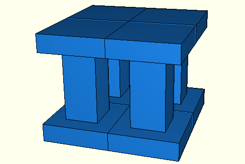
You can create a matrix of copied instances by creating copies in a second direction; for example, the Y-direction. The options are the same as for the first direction; you can control the number of copies, the spacing, and the orientation. By default, the first direction is the X-axis and the second direction is the Y-axis. For example, Figure 13–15 illustrates how a part instance can be patterned in both the X- and Y-axes.
Radial pattern
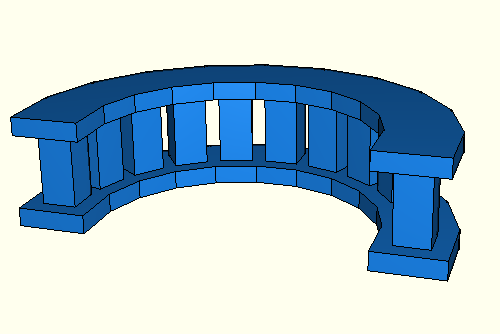
A radial pattern positions the new instances in a circular pattern. You can specify the number of instances, and you can specify the angle between the first and last copy, where a positive angle corresponds to a counterclockwise direction. For example, Figure 13–16 illustrates a radial pattern of the same part instances that appear in Figure 13–15.
By default, ABAQUS/CAE creates the radial pattern about the Z-axis. Alternatively, you can select a line from the assembly that defines the axis of the circular pattern.If you create a pattern of instances that are touching and you want to treat the pattern as a single part, you must use the Merge/Cut tool to merge all of the part instances in the pattern into a single part instance. For example, the instances in the radial pattern illustrated in Figure 13–16 overlapped each other and have been merged into a single part instance. For more information, see “Merging and cutting part instances,” Section 13.6. If you do not merge the part instances, the pattern may include duplicate faces or nodes where the instances touch.
If the original part instance includes a set or surface, you can use the merge functionality to create a new set or surface that includes all of the similar entities from the pattern of instances. For example, if the top face of the original part instance is included in a surface, you can create a new surface that merges all of the top surfaces from all of the instances in the pattern into a single surface. Surfaces are listed under part name or under the Assembly in the Model Tree. As a result, the Model Tree is a convenient tool for selecting a group of surfaces.
You will find it more convenient to use dependent part instances when you create a linear or radial pattern of instances. When you mesh the original part, ABAQUS/CAE applies the same mesh to each instance in the pattern. In contrast, if you create a pattern of independent instances, you must mesh each instance individually. For more information, see “What is the difference between a dependent and an independent part instance?,” Section 13.3.2.