
Select Shape![]() Cut
Cut![]() Circular Hole from the main menu bar to cut a circular hole through the part in the current viewport. The circular hole tool is always available, regardless of the modeling space of the part in the current viewport.
Circular Hole from the main menu bar to cut a circular hole through the part in the current viewport. The circular hole tool is always available, regardless of the modeling space of the part in the current viewport.
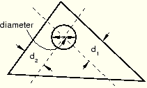
You cut a circular hole by specifying the distance from two selected straight edges and specifying the diameter of the hole, as shown in the following figure:
If the current viewport contains a two-dimensional or axisymmetric planar part, the hole always passes through all of the part. However, if the current viewport contains a three–dimensional part, ABAQUS/CAE prompts you to select the type of cut. You can select either Through All or Blind to define the cut depth.
The distance from the hole to each edge, the diameter of the hole, and the depth of a blind hole are the features that define a circular hole, and all three can be modified using the Feature Manipulation toolset. You cannot change the type of cut—through all or blind—after the cut has been created.
To cut a circular hole:
From the main menu bar, select Shape![]() Cut
Cut![]() Circular Hole.
Circular Hole.
ABAQUS/CAE displays prompts in the prompt area to guide you through the procedure.
Tip:
You can also cut a circular hole using the ![]() tool, located with the cut tools in the Part module toolbox. For a diagram of the tools in the Part module toolbox, see “Using the Part module toolbox,” Section 11.17.
tool, located with the cut tools in the Part module toolbox. For a diagram of the tools in the Part module toolbox, see “Using the Part module toolbox,” Section 11.17.
If the current viewport contains a two-dimensional part, select the first edge from which to position the center of the hole.
If the current viewport contains a three-dimensional part, you must do the following:
From the buttons in the prompt area, select one of the following types of cut:
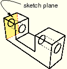
Click Through All to cut a circular hole that extends from a selected face in a selected direction through the part. A through cut is illustrated in the following example:
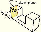
Click Blind to cut a circular hole that extends from a selected face in a selected direction but only to a specified depth. A blind cut is illustrated in the following example:
Select the face from which the hole will be cut.
Tip:
If you are unable to select the desired face, you can change the selection behavior by clicking the selection options tool ![]() in the prompt area. For more information, see “Using the selection options,” Section 6.3.
in the prompt area. For more information, see “Using the selection options,” Section 6.3.
An arrow appears, indicating the direction of the axis of the cut hole.
From the buttons in the prompt area, click Flip to reverse the arrow, if necessary. Click OK to accept the indicated direction.
Tip: If the arrow direction is difficult to see, use the rotate tool to rotate the part.
Select the first edge from which to position the center of the hole. The selected edges need not lie in the same plane as the selected face, but they must not be perpendicular to it.
In the text field in the prompt area, type the distance from the selected edge to the center of the hole.
Select the second edge from which to position the center of the hole. The two edges must not be parallel.
In the text field in the prompt area, type the distance from the selected edge to the center of the hole.
In the text field in the prompt area, type the diameter of the hole.
If the current viewport contains a two–dimensional or axisymmetric planar part, ABAQUS/CAE cuts the part with the circular hole.
If the current viewport contains a three–dimensional part and you selected a blind cut, a default hole depth appears in the prompt area. Click mouse button 2 to accept the default value, or enter a new hole depth.
The part returns to its original orientation with the circular hole cut from the selected face.
