If you accept the default Specify tangencies method for a loft, you can choose from several loft tangency options. Loft tangency affects the angle at which the loft faces leave the first loft section and approach the last section. The effect of tangency settings is transient, diminishing in proportion to the distance from the start or end section. The shape of the loft feature between any intermediate sections is unaffected by the loft tangency.
You can set all of the loft tangency options except None independently for the starting and ending section. For example, you can set the start tangency to Normal and the end tangency to Radial. You can choose from the following options to define the loft tangency:
None
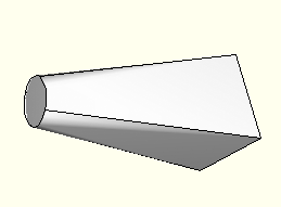
None is the default setting, and it is the only tangency setting that can be used with nonplanar sections. If you choose None, you must use it for both the start and the end tangency. None applies no conditions to the shape or direction of the loft. The edges of the loft feature will make a linear approach from the starting section to the second section and from the next-to-last section to the last section as shown in Figure 11–54.
Normal
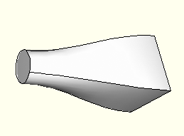
The Normal setting forces the faces created by the lofted edges to be at 90° to the first loft section as they are initially lofted toward the second section. Similarly, this setting forces the faces to be at 90° as they approach the last section of the loft feature. If you set Start Tangency to Normal, the initial part of the lofted feature will be similar to a straight extrusion as shown in Figure 11–55.
Radial
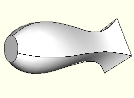
The Radial setting forces the faces created by the lofted edges to be at 0° to the first loft section as they are initially lofted toward the second section. Similarly, this setting forces the faces to be at 0° as they approach the last section of the loft feature. Thus, the faces initially radiate outward from the starting loft section or inward toward the ending loft section. If you set Start Tangency to Radial, the initial part of the lofted feature will be similar to an extrusion with a draft angle approaching 90° as shown in Figure 11–56.
Figure 11–56 A loft feature with radial tangency at the left end and normal tangency at the right end.
Warning: If you attempt to create a loft feature with only two loft sections and a dissimilar number of vertices, setting both Start Tangency and End Tangency to Radial may cause the loft feature to fail.
Specify
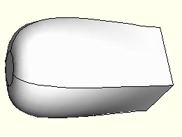
The Specify setting allows you to control both the Angle applied to the lofted edges and the Magnitude % that represents a relative distance through which the angle will affect the loft. If you set Start Tangency to Specify, the initial part of the lofted feature will be similar to an extrusion with a draft angle of Angle degrees as shown in Figure 11–57.
Figure 11–57 shows a Start Tangency angle of 45° (left) and an End Tangency angle of 135° (right), both applied with magnitudes of 25%. For reference, a Normal tangency setting corresponds to specifying an angle of 90° and a magnitude of 25% and a Radial tangency setting corresponds to specifying an angle of 0° and a magnitude of 25%.The angle of the loft faces at any point depends on the Angle and Magnitude % settings, the distance between consecutive loft sections, and the severity of change between the loft sections. Depending on these conditions, the requirement to make a smooth transition from one loft section to the next may override some loft tangency effects. If you require greater control over the shape of the loft, use the Select path method to define paths that the loft feature will follow exactly.