A part created in ABAQUS/CAE has a feature-based representation. A feature is a meaningful piece of the design and provides the engineer with a convenient and natural way to build and modify a part. Parts created in ABAQUS/CAE are constructed from an ordered list of features and the parameters that define the geometry of each feature. You select from the following shape features to build a part in the Part module:
Solids
Shells
Wires
Cuts
Blends
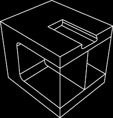
The following sequence illustrates how the three-dimensional part in Figure 11–1 would be constructed using features available in ABAQUS/CAE:
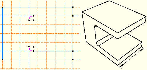
The first feature you create while building a part is called the base feature; you construct the remainder of the part by adding more features that either modify or add detail to the base feature. In this example the base feature is a U-shaped part; the user sketched a two-dimensional profile and extruded it to form the base feature, as shown in Figure 11–2.
The sketch and the extrusion depth (a) are the modifiable parameters that define the base feature. You can revisit the base feature and change its size or shape by using the Feature Manipulation toolset to modify either the section sketch or the extrusion distance. If desired, you can delete the base feature and sketch a new shape.
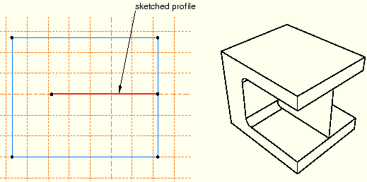
A stiffening web is added as a shell feature. The user sketched a line on one of the internal faces and extruded the sketch to the opposite face, as shown in Figure 11–3. The sketch is the only modifiable parameter that defines the shell feature.
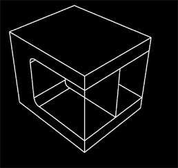
Rods are added to the corners as wire features. The wire was created by connecting two points that the user selected, as shown in Figure 11–4. Wires created in this way have no modifiable parameters; they must be deleted and recreated if you need to change them.
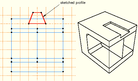
A blind cut is cut into the top of the clamp. The user sketched a two-dimensional profile, and the profile was extruded into the clamp through a specified distance, as shown in Figure 11–5. The sketch and the depth of the slot are the modifiable parameters that define the blind cut feature.
The edges of the cut are rounded. The user selected the edges to round and provided the radius of the round, as shown in Figure 11–6. The radius is the modifiable parameter that defines the round feature.
If the geometry of a new feature depends on an existing feature, ABAQUS/CAE creates a parent-child relationship between the features. The new feature is the child, and the feature it depends on is the parent. For example, in the part described above the round feature is a child of the cut feature. If you change the position or size of the cut, the edges remain rounded. Similarly, if you delete the cut, ABAQUS/CAE also deletes the rounds.
If you modify a parent feature, the modification may invalidate children of the parent feature. For example, in the part described above if you were to increase the depth of the cut so that it became a through cut, you would lose the fillets along its edges; that is, the fillets would fail to regenerate after the modification. ABAQUS/CAE offers you the following two choices:
Keep the changes to the parent feature but suppress the features that failed to regenerate. Children of the suppressed features will also be suppressed.
Abort the modification of the parent feature and return to the state of the last successful regeneration.