In complicated models, selecting individual faces or edges from a native part or selecting element faces or nodes from an orphan mesh can be time consuming and prone to error. For example, when creating a surface from an orphan mesh, you must select the individual element faces that make up the surface and append them to your selection. To speed up the selection process, ABAQUS/CAE provides the angle method for selecting multiple faces, edges, elements, element faces, or nodes.
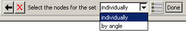
When you are performing a task that allows you to pick more than one face or edge from a native part or more than one element, element face, or node from an orphan mesh, ABAQUS/CAE displays a field in the prompt area. The field allows you to choose between the two selection methods—individually and by angle, as shown in Figure 6–4.
The angle method is a two-step process:In the prompt area you enter an angle (from 0° to 90°).
From the part or assembly you select a face, edge, element face, or node.
For example, to select the edges of a regular hexagon, you first enter an angle greater than 60° (since each adjacent edge must be rotated 60° to form the shape from a straight wire) and select one of the edges. ABAQUS/CAE then selects every adjacent edge since none of the angles are equal to or exceed the angle that you entered.
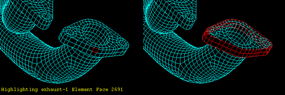
Figure 6–5 illustrates an exhaust manifold represented by an orphan mesh and the effect of the angle method after you select an element on the flange and an angle of 90°.
After you use the angle method, you can click the individually method in the prompt area and [Shift]+Click on individual faces, edges, elements, element faces, or nodes to append them to your selection. You can also [Ctrl]+Click on items to unselect them. In addition, you can continue to use the angle method and use [Shift]+Click to append faces, edges, elements, element faces, or nodes to your selection. You can keep the same angle, or you can change the angle while you continue to append items. For more information, see “Combining selection techniques,” Section 6.2.4.
In the Sketch module, the angle method is available only when you are selecting objects from the underlying part or assembly. When you are selecting edges in the sketch, the chain method replaces the angle method. You use the chain method to select a group of edges that are connected end-to-end, like the links of a chain. For more information on the chain method, see “Using the chain method to select edges in the Sketcher,” Section 19.4.6.