When you select the rotate tool ![]() and the viewport in which to work, ABAQUS/CAE enters rotate mode. In this mode the cursor changes to two curved arrows, and a large circle appears in the viewport. To define the center of rotation, you can enter its coordinates directly or select a point from the viewport. Otherwise, ABAQUS/CAE will rotate the view about the camera target, which normally coincides with the center of the viewport. If you select a center of rotation by selecting a point (or a node in the Visualization module) from the viewport or entering coordinates, it overrides the camera target and remains selected until you select a new center, display a different object, or choose the default rotation method. Your view of the model rotates as you drag the cursor, and a rubberband line indicates the amount and the direction of rotation. As you rotate your view of the model, the view triad indicates the orientation of the global coordinate system.
and the viewport in which to work, ABAQUS/CAE enters rotate mode. In this mode the cursor changes to two curved arrows, and a large circle appears in the viewport. To define the center of rotation, you can enter its coordinates directly or select a point from the viewport. Otherwise, ABAQUS/CAE will rotate the view about the camera target, which normally coincides with the center of the viewport. If you select a center of rotation by selecting a point (or a node in the Visualization module) from the viewport or entering coordinates, it overrides the camera target and remains selected until you select a new center, display a different object, or choose the default rotation method. Your view of the model rotates as you drag the cursor, and a rubberband line indicates the amount and the direction of rotation. As you rotate your view of the model, the view triad indicates the orientation of the global coordinate system.
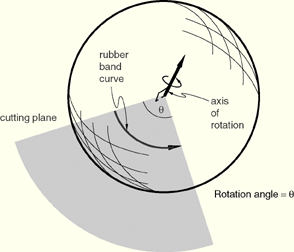
The circle that is drawn when you enter rotate mode represents the silhouette of an imaginary sphere that surrounds the object. When you drag the mouse inside the circle, you might imagine that you are actually rotating the sphere, as you would a trackball. Your model is attached to the center of the sphere, so that rotating the sphere causes your view of the model to rotate as well.
You determine the axis of rotation as you move the cursor over the surface of the imaginary sphere. The rubberband line represents the intersection of a cutting plane with the sphere's surface, and the rotation axis is normal to this cutting plane. The angle of rotation is equal to the angle made by the rubberband line on the sphere's surface, so that dragging all the way across the circle produces a 180° rotation. Figure 5–5 illustrates the imaginary sphere and a rubberband line being dragged across its surface.
When you drag outside the circle, the rubberband line is superimposed on the edge of the circle, and your view of the object simply rotates about an axis normal to the screen and passing through the center of the circle. In the same way as it does for dragging inside the circle, the rubberband line represents the angle through which the object has rotated.
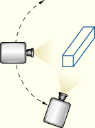
Using the default mode of view rotation is comparable to rotating the camera around the camera target or selected center of rotation, as shown in Figure 5–6.
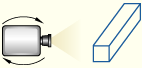
The alternate mode of the rotate tool, accessed by holding [Shift] while performing the manipulation, rotates the camera about itself instead of the camera target, as shown in Figure 5–7. This moves the camera target and frustum without regard to the position of objects in the original view.Rotating the camera about itself is most useful when you are in movie mode and the camera is positioned inside the model. In this position, moving the camera target and frustum brings different portions of the interior of the model into view.Note: If you have selected a point as the center of rotation, your selection overrides the alternate mode of rotation.
In either mode, it is usually easier to obtain a desired rotation by performing a sequence of smaller rotations rather than one large one. If you need to abandon the rotation and return to a known orientation, use either the predefined views in the Views toolbox ![]() or the cycle view tool
or the cycle view tool ![]() . Using any of the predefined views will also reset the camera target to the center of the model.
. Using any of the predefined views will also reset the camera target to the center of the model.