Product: ABAQUS/Standard
The pore fluid contact property models:
are typically used in geotechnical applications, where pore pressure continuity between material on opposite sides of an interface must be maintained;
ensure complete continuity of the pore fluid pressure between the two bodies;
can be used only with element-based contact;
can be defined on the surface of either coupled pore fluid diffusion/stress elements or regular stress/displacement continuum elements; and
assume that there is no fluid flowing tangentially to the surface.
Element-based surfaces, contact pairs, and contact property models can be used to define coupled pore fluid-mechanical contact interactions in ABAQUS/Standard. All of the contact pair options and all the contact property models that are pertinent to the pure mechanical contact interaction can be used for the coupled pore fluid-mechanical interaction. Both small and finite sliding can be modeled.
| Input File Usage: | *CONTACT PAIR, INTERACTION=interaction_name surface_1, surface_2 *SURFACE INTERACTION, NAME=interaction_name |
The pore fluid contact property models ensure continuity of the pore pressures on opposite sides of a contact interface at all times:
![]()
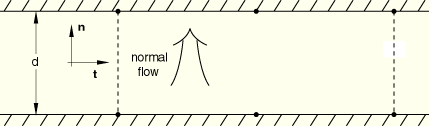
The flow patterns of the pore fluid in the interface element are shown in Figure 30.4.1–1. ABAQUS/Standard assumes that pore fluid does not flow tangentially along the interface. In steady-state analysis this assumption implies that all fluid flowing out of one surface flows into the other. In transient analysis the flow into the interface is balanced with the rate of separation of the two surfaces.
The contact pressure is effective; it does not include the pore fluid pressure contribution.
Zero tangential fluid flow occurs at the boundaries of the interface. However, the pore pressure can be prescribed at the boundaries, resulting in inward or outward flow across the boundary into the space between the surfaces.
The pore fluid contact elements can be used to model the interface between normal stress/displacement elements and coupled pore fluid/stress elements. In this case the surface with regular elements will be considered completely impermeable, and only flow into or out of the pore pressure elements is considered.
The contact pressure is total; i.e., it includes both effective structural and pore fluid pressure contributions. For the computation of friction, only the effective contact pressure is used.
You can write the contact surface variables associated with the interaction of contact pairs to the ABAQUS/Standard data (.dat), results (.fil), and output database (.odb) files. In addition to the surface variables associated with the mechanical contact analysis (shear stresses, contact pressures, etc.) several pore fluid-related variables (such as pore fluid volume flux per unit area) on the contact interface can be reported. A detailed discussion of these output requests can be found in “Surface output from ABAQUS/Standard” in “Output to the data and results files,” Section 4.1.2, and “Surface output” in “Output to the output database,” Section 4.1.3.
ABAQUS/Standard provides the following output variables related to the pore fluid interaction of surfaces:
PFL | Pore volume flux per unit area leaving the slave surface. |
PFLA | PFL multiplied by the area associated with the slave node. |
PTL | Time integrated PFL. |
PTLA | Time integrated PFLA. |
TPFL | Total pore volume flux leaving the slave surface. |
TPTL | Time integrated TPFL. |