Products: ABAQUS/Standard ABAQUS/Explicit ABAQUS/CAE
The embedded element technique:
is used to specify an element or a group of elements that lie embedded in a group of host elements whose response will be used to constrain the translational degrees of freedom of the embedded nodes (i.e., nodes of embedded elements);
can be used in geometrically linear or nonlinear analysis;
is not available for host elements with rotational degrees of freedom;
can be used to model a set of rebar-reinforced membrane, shell, or surface elements that lie embedded in a set of three-dimensional solid (continuum) elements; a set of truss or beam elements that lie embedded in a set of solid elements; or a set of solid elements that lie embedded in another set of solid elements;
will not constrain rotational degrees of freedom of the embedded nodes when shell or beam elements are embedded in solid elements; and
can be imported from ABAQUS/Standard into ABAQUS/Explicit and vice versa.
The embedded element technique is used to specify that an element or group of elements is embedded in “host” elements. The embedded element technique can be used to model rebar reinforcement. ABAQUS searches for the geometric relationships between nodes of the embedded elements and the host elements. If a node of an embedded element lies within a host element, the translational degrees of freedom at the node are eliminated and the node becomes an “embedded node.” The translational degrees of freedom of the embedded node are constrained to the interpolated values of the corresponding degrees of freedom of the host element. Embedded elements are allowed to have rotational degrees of freedom, but these rotations are not constrained by the embedding. Multiple embedded element definitions are allowed.
Different element types can be used in the element set containing embedded elements and the element set containing the host elements. However, all the host elements can have only translational degrees of freedom, and the number of translational degrees of freedom at a node on the embedded element must be identical to the number of translational degrees of freedom at a node on the host element. The following general types of “embedded elements-in-host elements” are provided:
Two-dimensional models:
Beam-in-solid
Solid-in-solid
Truss-in-solid
Axisymmetric models:
Membrane-in-solid (ABAQUS/Standard only)
Shell-in-solid
Solid-in-solid
Surface-in-solid (ABAQUS/Standard only)
Three-dimensional models:
Beam-in-solid
Membrane-in-solid
Shell-in-solid
Solid-in-solid
Surface-in-solid
Truss-in-solid
By default, the elements in the vicinity of the embedded elements are searched for elements that contain embedded nodes; the embedded nodes are then constrained by the response of these host elements. To preclude certain elements from constraining the embedded nodes, you can define a host element set; the search will be limited to this subset of the host elements in the model. This feature is strongly recommended if the embedded nodes are close to discontinuities in the model (cracks, contact pairs, etc.).
| Input File Usage: | *EMBEDDED ELEMENT, HOST ELSET=name |
The *EMBEDDED ELEMENT option must be included in the model definition portion of the input file. Multiple *EMBEDDED ELEMENT options are allowed. |
| ABAQUS/CAE Usage: | Interaction module: Create Constraint: Embedded region: choose Select Region from the prompt area when selecting the host region |
You must specify the embedded elements. Individual elements or element sets can be specified.
An embedded element may share some nodes with host elements. These nodes, however, will not be considered to be embedded nodes.
| Input File Usage: | *EMBEDDED ELEMENT embedded elements |
| ABAQUS/CAE Usage: | Interaction module: Create Constraint: Embedded region: select the embedded region |
A geometric tolerance is used to define how far an embedded node can lie outside the regions of the host elements in the model. By default, embedded nodes must lie within a distance calculated by multiplying the average size of all non-embedded elements in the model by 0.05; however, you can change this tolerance.
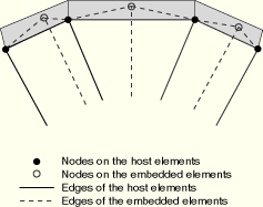
You can define the geometric tolerance as a fraction of the average size of all non-embedded elements in the model. Alternatively, you can define the geometric tolerance as an absolute distance in the length units chosen for the model. If you specify both exterior tolerances, ABAQUS uses the tighter tolerance of the two. The average size of all the non-embedded elements is calculated and multiplied by the fractional exterior, which is then compared to the absolute exterior tolerance to determine the tighter tolerance of the two. The exterior tolerance for embedded elements in host elements is indicated by the shaded region in Figure 28.4.1–1.
If an embedded node is located inside the specified tolerance zone, the node is constrained to the host elements. The position of this node will be adjusted to move the node precisely onto the host elements. If an embedded node is located outside the specified tolerance zone, an error message will be issued.
| Input File Usage: | Use the following option to define the tolerance as a fraction: |
*EMBEDDED ELEMENT, EXTERIOR TOLERANCE=tolerance Use the following option to define the tolerance as an absolute distance: *EMBEDDED ELEMENT, ABSOLUTE EXTERIOR TOLERANCE=tolerance |
| ABAQUS/CAE Usage: | Interaction module: Create Constraint: Embedded region: Fractional exterior tolerance or Absolute exterior tolerance |
If an embedded node lies close to an element edge or an element face within a host element, it is computationally efficient to make a small adjustment to the position of the embedded node so that the node will lie precisely on the edge or face of the host element. A small tolerance, below which the weight factors of the nodes on a host element associated with an embedded node will be zeroed out, is defined. The small weight factors will be redistributed to the other nodes on the host element in proportion to their initial weights, and the position of the embedded node will be adjusted based on the new weight factors. This adjustment is performed only at the start of the analysis and does not create any strain in the model. It is most useful for making small adjustments to make the embedded nodes lie on the edge or face of a host element. If a large nondefault value of the roundoff tolerance is used to make significant adjustments to the positions of the embedded nodes, you should carefully review the mesh obtained after adjusting.
| Input File Usage: | *EMBEDDED ELEMENT, ROUNDOFF TOLERANCE=tolerance |
| ABAQUS/CAE Usage: | Interaction module: Create Constraint: Embedded region: Weight factor roundoff tolerance |
In ABAQUS/Standard if an embedded node is also tied by multi-point, equation, kinematic coupling, surface-based tie, or rigid body constraints, an overconstraint is introduced and an error message will be issued. If a boundary condition is applied to an embedded node, the embedded element definition always takes precedence. The boundary condition will be neglected, and a warning message will be issued.
The following limitations exist for the embedded element technique:
Elements with rotational degrees of freedom (except axisymmetric elements with twist) cannot be used as host elements.
Rotational, temperature, pore pressure, acoustic pressure, and electrical potential degrees of freedom at an embedded node are not constrained.
Host elements cannot be embedded themselves.
The material defined for the host element is not replaced by the material defined for the embedded element at the same location of the integration point.
Additional mass and stiffness due to the embedded elements are added to the model.
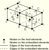
Consider the example in Figure 28.4.1–2.
Elements 3 (truss) and 4 (membrane) lie embedded in elements 1 and 2. Element 1 is formed by nodes a, b, c, d, e, f, g, and h; element 2 is formed by nodes e, f, g, h, i, j, k, and l; element 3 is formed by nodes A and B; and element 4 is formed by nodes C, D, E, and F. If the host element set includes elements 1 and 2 and the embedded element sets contain elements 3 and 4, respectively, ABAQUS will attempt to find if there are any embedded nodes (A, B, C, D, E, and F) lying within host elements 1 or 2. If node A is found to be lying close to the a-b-f-e face of element 1, all the degrees of freedom at node A are constrained to nodes a, b, f, and e, with appropriate weight factors being determined based on the geometric location of node A in element 1. Similarly, if node B is found to be lying inside element 1 and node E is found to be lying close to the g–k edge of element 2, respectively, all the degrees of freedom at node B are constrained to nodes a, b, c, d, e, f, g, and h, and all the degrees of freedom at node E are constrained to nodes g and k, with appropriate weight factors being determined based on the geometric location of node B in element 1 and the geometric location of node E on the g–k edge of element 2, respectively.You should make sure that all the nodes on the embedded elements are properly constrained to nodes on the host elements. This can be verified by performing a data check analysis (see “Execution procedure for ABAQUS/Standard and ABAQUS/Explicit,” Section 3.2.2). For each embedded node a list of nodes that are used to constrain this node and the associated weight factors are output to the data file during the data check analysis. An error message is issued if an embedded node is not constrained.
*HEADING
…
*NODE
Data line to define the nodal coordinates
*ELEMENT, TYPE=C3D8, ELSET=SOLID3D
Data line to define the solid elements
*ELEMENT, TYPE=T3D2, ELSET=TRUSS
Data line to define the truss elements
*ELEMENT, TYPE=M3D4, ELSET=MEMB
Data line to define the membrane elements
*EMBEDDED ELEMENT, EXTERIOR TOLERANCE=tolerance, HOST ELSET=SOLID3D
TRUSS, MEMB
*STEP
*STATIC (or any other allowable procedure)
Data line to define step time and control incrementation
…
*END STEP