Products: ABAQUS/Standard ABAQUS/CAE
Pore fluid flow can be prescribed in coupled pore fluid diffusion/stress analysis (see “Coupled pore fluid diffusion and stress analysis,” Section 6.7.1) and in the geostatic stress field procedure (see “Geostatic stress state,” Section 6.7.2). Pore fluid flow can be prescribed by:
defining seepage coefficients and sink pore pressures on element faces or surfaces;
defining drainage-only seepage coefficients on element faces or surfaces that are applied only when surface pore pressures are positive; or
prescribing an outward normal flow velocity directly at nodes, on element faces, or on surfaces.
In consolidation analysis you can provide seepage coefficients and sink pore pressures on element faces or surfaces to control normal pore fluid flow from the interior of the region modeled to the exterior of the region.
The surface condition assumes that the pore fluid flows in proportion to the difference between the current pore pressure on the surface, ![]() , and some reference value of pore pressure,
, and some reference value of pore pressure, ![]() :
:
![]()
![]()
is the component of the pore fluid velocity in the direction of the outward normal to the surface;
![]()
is the seepage coefficient;
![]()
is the current pore pressure at this point on the surface; and
![]()
is a reference pore pressure value.
To define element-based pore fluid flow, specify the element or element set name; the distributed load type; the reference pore pressure, ![]() ; and the reference seepage coefficient,
; and the reference seepage coefficient, ![]() . The face of the elements upon which the normal flow is enforced is identified by a seepage distributed load type. The seepage types available depend on the element type (see Part VI, “Elements”).
. The face of the elements upon which the normal flow is enforced is identified by a seepage distributed load type. The seepage types available depend on the element type (see Part VI, “Elements”).
| Input File Usage: | *FLOW element number or element set name, Qn, |
| ABAQUS/CAE Usage: | Pore fluid flow cannot be defined as a function of the current pore pressure in ABAQUS/CAE. |
To define surface-based pore fluid flow, specify a surface name, the seepage flow type, the reference pore pressure, and the reference seepage coefficient. The element-based surface (see “Defining element-based surfaces,” Section 2.3.2) contains the element and face information.
| Input File Usage: | *SFLOW surface name, Q, |
| ABAQUS/CAE Usage: | Pore fluid flow cannot be defined as a function of the current pore pressure in ABAQUS/CAE. |
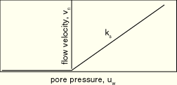
Drainage-only flow types can be specified for element-based or surface-based pore fluid flow to indicate that normal pore fluid flow occurs only from the interior to the exterior region of the model. The drainage-only flow surface condition assumes that the pore fluid flows in proportion to the magnitude of the current pore pressure on the surface, ![]() , when that pressure is positive:
, when that pressure is positive:
![]()
![]()
is the component of the pore fluid velocity in the direction of the outward normal to the surface;
![]()
is the seepage coefficient; and
![]()
is the current pore pressure at this point on the surface.
Figure 27.4.6–1 illustrates this pore pressure–velocity relationship. This surface condition is designed for use with the total pore pressure formulation (see “Coupled pore fluid diffusion and stress analysis,” Section 6.7.1), mainly for cases where the phreatic surface intersects an exterior surface that is free to drain. See “Calculation of phreatic surface in an earth dam,” Section 9.1.2 of the ABAQUS Example Problems Manual, for an example of this type of calculation.
When surface pore pressures are negative, the constraint will properly enforce the condition that no fluid can enter the interior region. When surface pore pressures are positive, the constraint will permit fluid flow from the interior to the exterior region of the model. When the seepage coefficient value, ![]() , is large, this flow will approximately enforce the requirement that the pore pressure should be zero on a freely draining surface. To achieve this condition, it is necessary to choose the value of
, is large, this flow will approximately enforce the requirement that the pore pressure should be zero on a freely draining surface. To achieve this condition, it is necessary to choose the value of ![]() to be much larger than a characteristic seepage coefficient for the material in the underlying elements:
to be much larger than a characteristic seepage coefficient for the material in the underlying elements:
![]()
k
is the permeability of the underlying material;
![]()
is the fluid specific weight; and
c
is a characteristic length of the underlying elements.
Values of ![]() will be adequate for most analyses. Larger values of
will be adequate for most analyses. Larger values of ![]() could result in poor conditioning of the model. In all cases the freely draining flow type represents discontinuously nonlinear behavior, and its use may require appropriate solution controls (see “Commonly used control parameters,” Section 7.2.2).
could result in poor conditioning of the model. In all cases the freely draining flow type represents discontinuously nonlinear behavior, and its use may require appropriate solution controls (see “Commonly used control parameters,” Section 7.2.2).
| ABAQUS/CAE Usage: | Pore fluid flow cannot be defined as a function of the current pore pressure in ABAQUS/CAE. |
Seepage coefficients and reference pore pressures can be added, modified, or removed as described in “Applying loads: overview,” Section 27.4.1.
The magnitude of the reference pore pressure, ![]() , can be controlled by referring to an amplitude curve. If different variations are needed for different portions of the flow, repeat the flow definition with each referring to its own amplitude curve. See “Applying loads: overview,” Section 27.4.1, and “Amplitude curves,” Section 27.1.2, for details.
, can be controlled by referring to an amplitude curve. If different variations are needed for different portions of the flow, repeat the flow definition with each referring to its own amplitude curve. See “Applying loads: overview,” Section 27.4.1, and “Amplitude curves,” Section 27.1.2, for details.
To define nonuniform flow, the variation of the reference pore pressure and the seepage coefficient as functions of position, time, pore pressure, etc. can be defined in user subroutine FLOW.
| ABAQUS/CAE Usage: | User subroutine FLOW is not supported in ABAQUS/CAE. |
You can directly prescribe an outward normal flow velocity, ![]() , across a surface or an outward normal flow at a node in consolidation analysis.
, across a surface or an outward normal flow at a node in consolidation analysis.
To prescribe an element-based seepage flow velocity, specify the element or element set name, the seepage type, and the outward normal flow velocity. The face of the element for which the seepage flow is being defined is identified by the seepage type. The seepage types available depend on the element type (see Part VI, “Elements”).
| Input File Usage: | *DFLOW element number or element set name, Sn, |
| ABAQUS/CAE Usage: | Element-based seepage flow velocity is not supported in ABAQUS/CAE. |
To prescribe a surface-based seepage flow velocity, specify a surface name, the seepage flow type, and the pore fluid velocity. The element-based surface (see “Defining element-based surfaces,” Section 2.3.2) contains the element and face information.
| Input File Usage: | *DSFLOW surface name, S, |
| ABAQUS/CAE Usage: | Load module: Create Load: choose Fluid for the Category and Surface pore fluid for the Types for Selected Step |
To prescribe node-based seepage flow, specify the node or node set name and the magnitude of the flow per unit time.
| Input File Usage: | *CFLOW node number or node set name, , magnitude of the flow per unit time |
| ABAQUS/CAE Usage: | Load module: Create Load: choose Fluid for the Category and Concentrated pore fluid for the Types for Selected Step |
Seepage flow velocities can be added, modified, or removed as described in “Applying loads: overview,” Section 27.4.1.
The magnitude of the seepage velocity, ![]() , can be controlled by referring to an amplitude curve. To specify different variations for different flows, repeat the seepage flow velocity or seepage flow definition with each referring to its own amplitude curve. See “Applying loads: overview,” Section 27.4.1, and “Amplitude curves,” Section 27.1.2, for details.
, can be controlled by referring to an amplitude curve. To specify different variations for different flows, repeat the seepage flow velocity or seepage flow definition with each referring to its own amplitude curve. See “Applying loads: overview,” Section 27.4.1, and “Amplitude curves,” Section 27.1.2, for details.
To define nonuniform element-based or surface-based flow, the variation of the seepage magnitude as a function of position, time, pore pressure, etc. can be defined in user subroutine DFLOW. If the optional seepage velocity, ![]() , is specified directly, this value is passed into user subroutine DFLOW in the variable used to define the seepage magnitude.
, is specified directly, this value is passed into user subroutine DFLOW in the variable used to define the seepage magnitude.
| ABAQUS/CAE Usage: | Load module: Create Load: choose Fluid for the Category and Concentrated pore fluid or Surface pore fluid for the Types for Selected Step: select region: Distribution: User-defined |