Product: ABAQUS/Standard
Drag chain elements:
are used for simulating the effects of drag chains on the seabed for near bottom bending simulation modeling; and
can be used in two-dimensional or three-dimensional problems.
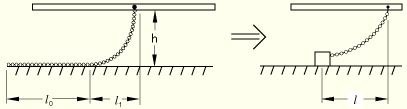
The drag chain is modeled as a concentrated weight on the seabed, with a chain between it and an attachment point on the pipe (see Figure 26.12.1–1).
Given a uniform drag chain of total length ![]() , weight per unit length w, and friction coefficient
, weight per unit length w, and friction coefficient ![]() between it and the seabed, attached to the pipeline at height h above the seabed, the length of chain on the seabed at slip,
between it and the seabed, attached to the pipeline at height h above the seabed, the length of chain on the seabed at slip, ![]() , is given by
, is given by
![]()
When the pipeline attachment point is directly above the weight, there will be no horizontal force or horizontal stiffness offered by a drag chain element; this position is assumed as the initial condition. As the pipe moves relative to the seabed, the horizontal force on the pipeline caused by the drag chain opposes the relative motion and gradually increases (an approximation to the catenary equation is used to relate the force to the offset ![]() ) until the drag chain slips when the force reaches the friction limit. The height, h, is assumed to be small compared to
) until the drag chain slips when the force reaches the friction limit. The height, h, is assumed to be small compared to ![]() .
.
Two- and three-dimensional drag chain elements are available.
Element DRAG2D assumes that the seabed is flat and parallel to the plane in which the pipe is moving; therefore, the seabed does not have to be modeled explicitly.
Element DRAG3D requires that the seabed be defined as an analytical rigid surface, which must be flat and parallel to the global (X, Y) plane and is considered to be fixed throughout the analysis.
The seabed is defined as an analytical rigid surface. This surface definition is used to determine if the chain touches the seabed, depending on the separation between the pipe node and the position of the seabed surface. See “Defining analytical rigid surfaces,” Section 2.3.4, for more information.
Since the seabed is considered to be fixed, boundary conditions must be applied to the rigid body reference node of the seabed surface, which is also the second node of the DRAG3D element.
| Input File Usage: | Use the following option to define the seabed surface for DRAG3D elements: |
*RIGID SURFACE In a model defined in terms of an assembly of part instances, the rigid surface definition that defines the seabed must appear inside the same part definition as the drag chain elements. |
For DRAG2D elements you specify the maximum horizontal length, ![]() , between the attachment point and the concentrated weight. At this length the weight will start to slip on the seabed. In addition, you specify the horizontal force between the weight and the seabed at slip (that is, the frictional limit).
, between the attachment point and the concentrated weight. At this length the weight will start to slip on the seabed. In addition, you specify the horizontal force between the weight and the seabed at slip (that is, the frictional limit).
For DRAG3D elements you specify the total length of the chain, the friction coefficient, and the weight per unit length of chain.
You must associate the drag chain behavior with a set of drag chain elements.
| Input File Usage: | *DRAG CHAIN, ELSET=name drag chain data |