Product: ABAQUS/Standard
Tube support elements:
are provided to model the interaction of a tube with a closely adjacent tube support, for cases where intermittent contact between the tube and the support may occur; and
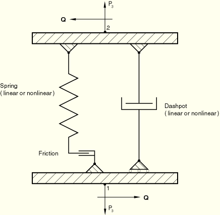
are made up of a spring/friction link (to simulate direct contact between the tube and the support) and a parallel dashpot (to simulate the effect of the fluid in the annulus between the tube and the support), as shown in Figure 26.9.1–1.
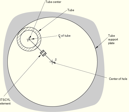
An ITSCYL element can be used to model a drilled hole support (see Figure 26.9.1–2).
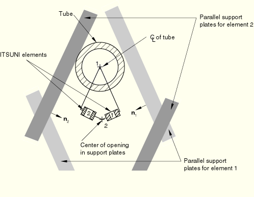
Several ITSUNI elements can be attached to the same node of the beam elements representing the tube to model the case of a tube support made up of a series of straight segments, as in an “egg-crate” design (see Figure 26.9.1–3).
Two types of tube support elements are provided.
ITSUNI is a “unidirectional” element, which always acts in a fixed direction in space. One node of the element must be located on the axis of the tube, which is modeled using beam elements; and the other node must be located equidistant between the two parallel support plates. The support plates are built into the ITSUNI element definition.
ITSCYL is a “cylindrical” element, which can be used to simulate the interaction between a circular tube and a circular hole. One node of the element must be located on the axis of the tube, which is modeled using beam elements, and the other node must be located at the center of the hole in the circular tube support plate. The circular hole is built into the ITSCYL element definition.
You define the diameter of the tube and other geometric quantities that define the ITS element. You must associate these quantities with a set of ITS elements.
In addition, you must define the behavior of the spring, friction link, and dashpot that make up a tube support element. The clearance between the tube and the support is built into the nonlinear spring definition.
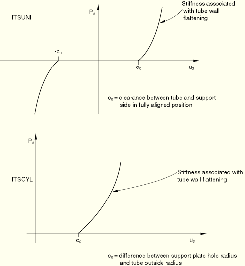
The spring in the ITS element is assumed to behave as shown in Figure 26.9.1–4. When there is no contact between the tube and the support, no force is transmitted by the spring; when the tube is in contact with the support, the force increases as the tube wall is deformed. This force can be modeled as a linear or a nonlinear function of the relative displacement between the axis of the tube and the center of the hole in the support. Relative displacements in the element are measured from the position when the tube and the hole in the support plate are aligned exactly—when the nodes of the element are at the same location.
If the friction force, the tube diameter, and the size of the hole in the support are all nonzero, the element will generate a moment about the axis of the tube and the tube support. Therefore, if the nodes of the element are not associated with beams or other elements that can carry the moment, the rotation should be set to zero with a boundary condition.