Product: ABAQUS/Standard
Distributing coupling elements:
can be used to distribute forces and moments on a reference node to a collection of nodes;
can be used to prescribe an average displacement and rotation to a collection of nodes;
can be used to distribute mass to a collection of nodes;
can control the force and mass distribution through the use of weight factors specified for each coupling node;
can be used to create a flexible coupling between structural and solid elements; and
can be used with two- or three-dimensional stress/displacement elements.
The distributing coupling element constrains the motion of the coupling nodes to the translation and rotation of the element node. This constraint is enforced in an average sense and in a way that enables control of the transmission of loads. These characteristics make the distributing coupling element useful in a number of applications:
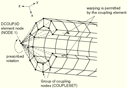
The element can be used to prescribe a displacement and rotation condition on a boundary in cases where relative motion among the nodes on the boundary is required. An example of such a case is prescribing a twist on the end of a structure that is expected to warp and/or deform within the end surface (see Figure 26.4.1–1).
The element can be used to provide, through the motion of the reference node, a weighted average of the motion of the coupling nodes.
The element can be used to distribute loads, where the load distribution can be described with moment-of-inertia expressions. Examples of such cases include the classic bolt-pattern and weld-pattern load distribution expressions.
The element can be used as a coupling between two parts (structural-solid) to transfer forces and moments. In comparison to MPCs and the kinematic coupling constraint, the distributing coupling element can be considered a more “flexible” connection.
Two- and three-dimensional distributing coupling elements are available. Element DCOUP2D describes behavior only in the global X–Y plane. Element DCOUP2D can be used in an axisymmetric analysis; however, its use requires care in selecting the load distributing weight factors. For example, a uniform axial load distribution to a structure would require specification of load distribution weight factors in proportion to the radius of the coupling nodes. Since the radius of these nodes will change with deformation, this use of DCOUP2D would only approximate the correct load distribution behavior in a large-displacement analysis.
To define a distributing coupling, you specify the coupling nodes to which loads and mass are to be distributed, along with the corresponding weighting of the distribution. A minimum of two coupling nodes is required.
| Input File Usage: | *DISTRIBUTING COUPLING, ELSET=name node number or node set, weight_factor_1 node number or node set, weight_factor_2 ... |
This example (see Figure 26.4.1–1) illustrates the use of the DCOUP3D element to impart a rotation to the surface of a structure that is expected to deform in a general way. In this case warping and motion within the plane of the end surface are expected to occur.
*ELEMENT, TYPE=DCOUP3D, ELSET=ROTATEELEMENT
1001, 1
*DISTRIBUTING COUPLING, ELSET=ROTATEELEMENT
COUPLESET, 1.0
…
*STEP, NLGEOM
…
*BOUNDARY
1, 6, 6, 1.0
…
*END STEP
The element distributes loads such that the resultants of the forces on the coupling nodes are equal to the forces and moments on the element node. For cases of more than a few coupling nodes, the distribution of the forces is not determined by equilibrium alone, and the user-specified weight factors are used to define the distribution. The weight factors are dimensionless and are normalized within each element so that the sum of all weight factors is one. As a consequence, the normalized weight factors describe the proportion of the total element force and moment that is transmitted through the particular coupling node. In the case of transmission of forces alone, the proportion of force transmitted through the node is simply the normalized weight factor. In the general case of transmission of forces and moments, the force distribution follows that of a classic bolt-pattern analysis, where the weight factors could be considered the areas of particular bolt cross-sections. Refer to “Distributing coupling elements,” Section 3.9.8 of the ABAQUS Theory Manual, for specific details of the load distribution.
In the example shown in Figure 26.4.1–1 the weight factor distribution chosen is homogeneous, with a value of 1.0. For the rotation depicted, a more accurate load distribution would reflect the fact that the shear forces on nodes near the edge of the slot will diminish to zero, which could be described by choosing individual weight factors for nodes near the slot edge. If the loading on the element were along the axis of the structure, the homogeneous distribution shown would be appropriate. For cases where different loading modes require different descriptions of the weight factor distribution, multiple distributing coupling elements with different element nodes and different weight factors can be used.
The distributing coupling element transmits moments at the element node as a force distribution among the coupling nodes, even if these nodes have rotational degrees of freedom. Thus, when the coupling node arrangement is colinear, the element is not capable of transmitting all components of a moment at the element node. Specifically, the moment component that is parallel to the colinear coupling node arrangement will not be transmitted. When this case arises, a warning message is issued that identifies the axis about which the element will not transmit a moment.
The mass distribution is analogous to the force distribution; the specified element mass is distributed to the coupling nodes in proportion to the weight factors.
| Input File Usage: | *DISTRIBUTING COUPLING, ELSET=name, MASS=total_element_mass node number or node set, weight_factor_1 node number or node set, weight_factor_2 ... |