Product: ABAQUS/Standard
Frame elements:
are 2-node, initially straight, slender beam elements intended for use in the elastic or elastic-plastic analysis of frame-like structures;
are available in two or three dimensions;
have elastic response that follows Euler-Bernoulli beam theory with fourth-order interpolation for the transverse displacements;
have plastic response that is concentrated at the element ends (plastic hinges) and is modeled with a lumped plasticity model that includes nonlinear kinematic hardening;
are implemented for small or large displacements (large rotations with small strains);
output forces and moments at the element ends and midpoint;
output elastic axial strain and curvatures at the element ends and midpoint and plastic displacements and rotations at the element ends only;
admit, optionally, a uniaxial “buckling strut” response where the axial response of the element is governed by a damaged elasticity model in compression and an isotropic hardening plasticity model in tension and where all transverse forces and moments are zero;
can switch to buckling strut response during the analysis (for pipe sections only); and
can be used in static, implicit dynamic, and eigenfrequency extraction analyses only.
Frame elements are designed to be used for small-strain elastic or elastic-plastic analysis of frame-like structures composed of slender, initially straight beams. Typically, a single frame element will represent the entire structural member connecting two joints. A frame element's elastic response is governed by Euler-Bernoulli beam theory with fourth-order interpolations for the transverse displacement field; hence, the element's kinematics include the exact (Euler-Bernoulli) solution to concentrated end forces and moments and constant distributed loads. The elements can be used to solve a wide variety of civil engineering design applications, such as truss structures, bridges, internal frame structures of buildings, off-shore platforms, and jackets, etc. A frame element's plastic response is modeled with a lumped plasticity model at the element ends that simulates the formation of plastic hinges. The lumped plasticity model includes nonlinear kinematic hardening. The elements can, thus, be used for collapse load prediction based on the formation of plastic hinges.
Slender, frame-like members loaded in compression often buckle in such a way that only axial force is supported by the member; all other forces and moments are negligibly small. Frame elements offer optional buckling strut response whereby the element only carries axial force, which is calculated based on a damaged elasticity model in compression and an isotropic hardening plasticity model in tension. This model provides a simple phenomenological approximation to the highly nonlinear geometric and material response that takes place during buckling and postbuckling deformation of slender members loaded in compression.
For pipe sections only, frame elements allow switching to optional uniaxial buckling strut response during the analysis. The criterion for switching is the “ISO” equation together with the “strength” equation (see “Buckling strut response for frame elements,” Section 3.9.3 of the ABAQUS Theory Manual). When the ISO and strength equations are satisfied, the elastic or elastic-plastic frame element undergoes a one-time-only switch in behavior to buckling strut response.
The orientation of the frame element's cross-section is defined in ABAQUS/Standard in terms of a local, right-handed (![]() ,
, ![]() ,
, ![]() ) axis system, where
) axis system, where ![]() is the tangent to the axis of the element, positive in the direction from the first to the second node of the element, and
is the tangent to the axis of the element, positive in the direction from the first to the second node of the element, and ![]() and
and ![]() are basis vectors that define the local 1- and 2-directions of the cross-section.
are basis vectors that define the local 1- and 2-directions of the cross-section. ![]() is referred to as the first axis direction, and
is referred to as the first axis direction, and ![]() is referred to as the normal to the element. Since these elements are initially straight and assume small strains, the cross-section directions are constant along each element and possibly discontinuous between elements.
is referred to as the normal to the element. Since these elements are initially straight and assume small strains, the cross-section directions are constant along each element and possibly discontinuous between elements.
For frame elements in a plane the ![]() -direction is always (0.0, 0.0, –1.0); that is, normal to the plane in which the motion occurs. Therefore, planar frame elements can bend only about the first axis direction.
-direction is always (0.0, 0.0, –1.0); that is, normal to the plane in which the motion occurs. Therefore, planar frame elements can bend only about the first axis direction.
For frame elements in space the approximate direction of ![]() must be defined directly as part of the element section definition or by specifying an additional node off the element's axis. This additional node is included in the element's connectivity list (see “Element definition,” Section 2.2.1).
must be defined directly as part of the element section definition or by specifying an additional node off the element's axis. This additional node is included in the element's connectivity list (see “Element definition,” Section 2.2.1).
If an additional node is specified, the approximate direction of ![]() is defined by the vector extending from the first node of the element to the additional node.
is defined by the vector extending from the first node of the element to the additional node.
If both input methods are used, the direction calculated by using the additional node will take precedence.
If the approximate direction is not defined by either of the above methods, the default value is (0.0, 0.0, –1.0).
The frame element's formulation includes the effect of large rigid body motions (displacements and rotations) when geometrically nonlinear analysis is selected (see “General and linear perturbation procedures,” Section 6.1.2). Strains in these elements are assumed to remain small.
For frame elements the geometric and material properties are specified together as part of the frame section definition. No separate material definition is required. You can choose one of the section shapes that is valid for frame elements from the beam cross-section library (see “Beam cross-section library,” Section 23.3.9). The valid section shapes depend upon whether elastic or elastic-plastic material response is specified or whether buckling strut response is included. See “Frame section behavior,” Section 23.4.2, for a complete discussion of specifying the geometric and material section properties.
| Input File Usage: | *FRAME SECTION, SECTION=section_type |
The mechanical response of a frame element includes elastic and plastic behavior. Optionally, uniaxial buckling strut response is available.
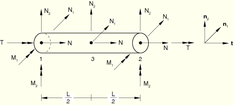
The elastic response of a frame element is governed by Euler-Bernoulli beam theory. The displacement interpolations for the deflections transverse to the frame element's axis (the local 1- and 2-directions in three dimensions; the local 2-direction in two dimensions) are fourth-order polynomials, allowing quadratic variation of the curvature along the element's axis. Thus, each single frame element exactly models the static, elastic solution to force and moment loading at its ends and constant distributed loading along its axis (such as gravity loading). The displacement interpolation along an element's axis is a second-order polynomial, allowing linear variation of the axial strain. In three dimensions the twist rotation interpolation along an element's axis is linear, allowing constant twist strain. The elastic stiffness matrix is integrated numerically and used to calculate 15 nodal forces and moments in three dimensions: an axial force, two shear forces, two bending moments, and a twist moment at each end node, and an axial force and two shear forces at the midpoint node. In two dimensions 8 nodal forces and moments exist: an axial force, a shear force, and a moment at each end, and an axial force and a shear force at the midpoint. The forces and moments are illustrated in Figure 23.4.1–1.
The plastic response of the element is treated with a “lumped” plasticity model such that plastic deformations can develop only at the element's ends through plastic rotations (hinges) and plastic axial displacement. The growth of the plastic zone through the element's cross-section from initial yield to a fully yielded plastic hinge is modeled with nonlinear kinematic hardening. It is assumed that the plastic deformation at an end node is influenced by the moments and axial force at that node only. Hence, the yield function at each node, also called the plastic interaction surface, is assumed to be a function of that node's axial force and three moment components only. No length is associated with the plastic hinge. In reality, the plastic hinge will have a finite size determined by the element's length and the specific loading that causes yielding; the hinge size will influence the hardening rate but not the ultimate load. Hence, if the rate of hardening and, thus, the plastic deformation for a given load are important, the lumped plasticity model should be calibrated with the element's length and the loading situation taken into account. For details on the elastic-plastic element formulation, see “Frame elements with lumped plasticity,” Section 3.9.2 of the ABAQUS Theory Manual.
You can obtain a frame element's response to uniaxial force only, based on linear elasticity, buckling strut response, and tensile yield. In that case all transverse forces and moments in the element are zero. For linear elastic response the element behaves like an axial spring with constant stiffness. For buckling strut response if the tensile axial force in the element does not exceed the yield force, the axial force in the element is constrained to remain inside a buckling envelope. See “Frame section behavior,” Section 23.4.2, for a description of this envelope. Inside the envelope the force is related to strain by a damaged elastic modulus. The cyclic, hysteretic response of this model is phenomenological and approximates the response of thin-walled, pipe-like members. When the element is loaded in tension beyond the yield force, the force response is governed by isotropic hardening plasticity. In reverse loading the response is governed by the buckling envelope translated along the strain axis by an amount equal to the axial plastic strain. For details of the buckling strut formulation, see “Buckling strut response for frame elements,” Section 3.9.3 of the ABAQUS Theory Manual.
The frame element uses a lumped mass formulation for both dynamic analysis and gravity loading. The mass matrix for the translational degrees of freedom is derived from a quadratic interpolation of the axial and transverse displacement components. The rotary inertia for the element is isotropic and concentrated at the two ends.
For buckling strut response a lumped mass scheme is used, where the element's mass is concentrated at the two ends; no rotary inertia is included.
When contact conditions play a role in a structure's behavior, frame elements have to be used with caution. A frame element has one additional internal node, located in the middle of the element. No contact constraint is imposed on this node, so this internal node may penetrate the surface in contact, resulting in a sagging effect.
The forces and moments, elastic strains, and plastic displacements and rotations in a frame element are reported relative to a corotational coordinate system. The local coordinate directions are the axial direction and the two cross-sectional directions. Output of section forces and moments as well as elastic strains and curvatures is available at the element ends and midpoint. Output of plastic displacement and rotations is available only at the element ends. You can request output to the output database (at the integration points only), to the data file, or to the results file (see “Output to the data and results files,” Section 4.1.2, and “Output to the output database,” Section 4.1.3). Since frame elements are formulated in terms of section properties, stress output is not available.