Products: ABAQUS/Standard ABAQUS/Explicit ABAQUS/CAE
A display body:
can be two-dimensional planar, axisymmetric, or three-dimensional;
is associated with a part instance and up to three reference nodes, such that the motion of the part instance is governed by the motion of the reference nodes;
is used for display purposes only and does not take part in the analysis;
can be used to make the analysis more efficient while improving visualization of analysis results; and
is especially useful for mechanism or multibody dynamic analyses.
A display body is a part instance that is used for display only. None of the nodes or elements of the instance take part in the analysis, but they are still available during postprocessing. The motion of the display body is governed by the motion of the associated reference nodes, if any. It behaves like a rigid body since the relative positions of the nodes and elements of the part instance remain constant throughout a simulation. The nodes and elements of the part instance cannot be used to define prescribed conditions, interactions, constraints, etc. Section properties do not have to be assigned to the elements.
A display body is useful in cases where the physical model is different from the idealized model used for the analysis. An idealized model may be difficult to visualize; it may help to include more details in the model for realistic postprocessing purposes. Display bodies allow this without increasing the analysis time.
Display bodies are especially useful in mechanism or multibody dynamics problems where rigid parts interact with each other via connectors. In such cases a part can be represented by a very simple rigid body and a more complex display body. In this case, the rigid body can be as simple as just a node, along with mass and rotary inertia elements attached to that node.
Display bodies can also be used to model stationary objects that are not involved in the analysis but aid in visualization.
You must specify the part instance to be made a display body.
| Input File Usage: | *DISPLAY BODY, INSTANCE=name |
| ABAQUS/CAE Usage: | Interaction module: Create Constraint: Display body: select part instance |
If the display body is not associated with any reference nodes, it will remain fixed in space during the analysis. However, you can specify that the motion of the display body should be governed by the motion of selected reference nodes. These nodes must belong to another part instance in the assembly. They cannot belong to another display body definition. If you specify only one reference node, the display body will translate and rotate based on the translations and rotations of that node during the analysis. If the reference node has no rotational degrees of freedom, the display body will not rotate during the analysis.
If you specify three reference nodes, the display body will translate and rotate based on the translations of all three nodes. The new position of the part instance at any time will be calculated from the new position and orientation of the coordinate system defined by the three reference nodes: the first node will be the origin, the second will be a point in the x-direction, and the third node will be a point in the X–Y plane. Care should be taken when specifying the three nodes so that they do not become colinear at any stage of the analysis. If this occurs, the position of the part instance may change abruptly through that increment.
| Input File Usage: | *DISPLAY BODY, INSTANCE=name first reference node number, second reference node number, third reference node number |
| ABAQUS/CAE Usage: | Interaction module: Create Constraint: Display body: select part instance, choose Follow single point or Follow three points, click Edit, and select the reference points |
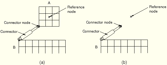
Display bodies can be used effectively in models containing rigid part instances that interact with each other using connector elements. Such models need both rigid bodies and display bodies. The rigid body should contain any nodes used by connectors, used to define mass and inertia properties, and used to apply loads or boundary conditions. The display body should contain the nodes and elements representing the physical part. Care should be taken to ensure that the nodes in the rigid body are not part of the display body. The reference node of the display body will typically be the same as the rigid body reference node.
Figure 2.8.1–1(a) illustrates a model containing rigid bodies and a display body.
Part instance A is included in a display body definition. Figure 2.8.1–1(b) shows the same model without the display body. This model will actually be involved in the analysis. The connector node and reference node form a rigid body that represents the analysis version of part instance A. Both these nodes are assembly-level nodes and are not included in the display body.The following input shows how display bodies can be used in a model with rigid part instances and connectors:
*ASSEMBLY
...
*INSTANCE, NAME=INST1
...
*END INSTANCE
*NODE, NSET=INST1-REFNODE
1001, -10, 0, 0
*NODE, NSET=INST1-CONNECTOR-NODE
1002, -5, -5, 0
*RIGID BODY, TIE NSET=INST1-CONNECTOR-NODE,
REF NODE=INST1-REFNODE
*DISPLAY BODY, INSTANCE=INST1
1001
...
*END ASSEMBLY