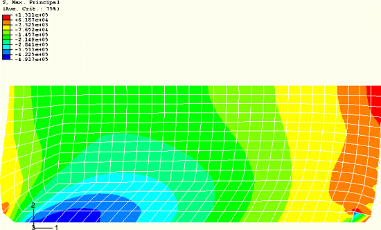
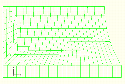
We know that the element distortions in the corners of the rubber mount are undesirable. The results in these areas are unreliable; and if the load were increased, the analysis might fail. These problems can be corrected by using a better mesh design. The mesh shown in Figure 10–65 is an example of an alternate mesh design that might be used to reduce element distortion in the bottom left corner of the rubber model. The issues surrounding the mesh distortion in the opposite corner are addressed in “Techniques for reducing volumetric locking,” Section 10.9. The elements in the bottom left-hand corner region are now much more distorted in the initial, undeformed configuration. However, as the analysis progresses and the elements deform, their shape actually improves. The displaced shape plot, shown in Figure 10–66, illustrates that the amount of element distortion in this region is reduced; the level of mesh distortion in the bottom right-hand corner of the rubber model is still significant.
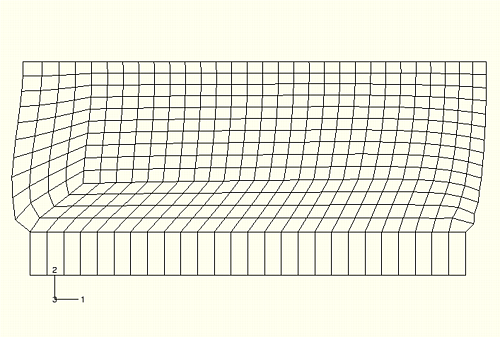
Figure 10–65 Modified mesh to minimize element distortions in the bottom left corner of the rubber model during the simulation.
Mesh design for large-distortion problems is more difficult than it is for small-displacement problems. A mesh must be produced where the shape of the elements is reasonable throughout the analysis, not just at the start. You must estimate how the model will deform using experience, hand calculations, or the results from a coarse finite element model.