A wide range of elements is available in ABAQUS. This extensive element library provides you with a powerful set of tools for solving many different problems. The elements available in ABAQUS/Explicit are a subset of those available in ABAQUS/Standard. This section introduces you to the five aspects of an element that influence how it behaves.
Each element is characterized by the following:
Family
Degrees of freedom (directly related to the element family)
Number of nodes
Formulation
Integration
Family
Figure 3–1 shows the element families most commonly used in a stress analysis. One of the major distinctions between different element families is the geometry type that each family assumes.
The element families that you will use in this guide—continuum, shell, beam, truss, and rigid elements—are discussed in detail in other chapters. The other element families are not covered in this guide; if you are interested in using them in your models, read about them in Part VI, “Elements,” of the ABAQUS Analysis User's Manual.
The first letter or letters of an element's name indicate to which family the element belongs. For example, the S in S4R indicates this is a shell element, while the C in C3D8I indicates this is a continuum element.
Degrees of freedom
The degrees of freedom (dof) are the fundamental variables calculated during the analysis. For a stress/displacement simulation the degrees of freedom are the translations at each node. Some element families, such as the beam and shell families, have rotational degrees of freedom as well. For a heat transfer simulation the degrees of freedom are the temperatures at each node; a heat transfer analysis, therefore, requires the use of different elements than a stress analysis, since the degrees of freedom are not the same.
The following numbering convention is used for the degrees of freedom in ABAQUS:
| 1 | Translation in direction 1 |
| 2 | Translation in direction 2 |
| 3 | Translation in direction 3 |
| 4 | Rotation about the 1-axis |
| 5 | Rotation about the 2-axis |
| 6 | Rotation about the 3-axis |
| 7 | Warping in open-section beam elements |
| 8 | Acoustic pressure, pore pressure, or hydrostatic fluid pressure |
| 9 | Electric potential |
| 11 | Temperature (or normalized concentration in mass diffusion analysis) for continuum elements or temperature at the first point through the thickness of beams and shells |
| 12+ | Temperature at other points through the thickness of beams and shells |
Axisymmetric elements are the exception, with the displacement and rotation degrees of freedom referred to as follows:
Directions r (radial) and z (axial) correspond to the global 1- and 2-directions, respectively, unless a local coordinate system has been defined at the nodes. See Chapter 5, “Using Shell Elements,” for a discussion of defining a local coordinate system at the nodes.In this guide our attention is restricted to structural applications. Therefore, only elements with translational and rotational degrees of freedom are discussed. For information on other types of elements (for example, heat transfer elements), consult the ABAQUS Analysis User's Manual.
Number of nodes—order of interpolation
Displacements, rotations, temperatures, and the other degrees of freedom mentioned in the previous section are calculated only at the nodes of the element. At any other point in the element, the displacements are obtained by interpolating from the nodal displacements. Usually the interpolation order is determined by the number of nodes used in the element.
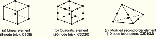
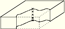
Elements that have nodes only at their corners, such as the 8-node brick shown in Figure 3–2(a), use linear interpolation in each direction and are often called linear elements or first-order elements.
Elements with midside nodes, such as the 20-node brick shown in Figure 3–2(b), use quadratic interpolation and are often called quadratic elements or second-order elements.
Modified triangular or tetrahedral elements with midside nodes, such as the 10-node tetrahedron shown in Figure 3–2(c), use a modified second-order interpolation and are often called modified or modified second-order elements.
Typically, the number of nodes in an element is clearly identified in its name. The 8-node brick element, as you have seen, is called C3D8; and the 8-node general shell element is called S8R. The beam element family uses a slightly different convention: the order of interpolation is identified in the name. Thus, a first-order, three-dimensional beam element is called B31, whereas a second-order, three-dimensional beam element is called B32. A similar convention is used for axisymmetric shell and membrane elements.
Formulation
An element's formulation refers to the mathematical theory used to define the element's behavior. In the absence of adaptive meshing all of the stress/displacement elements in ABAQUS are based on the Lagrangian or material description of behavior: the material associated with an element remains associated with the element throughout the analysis, and material cannot flow across element boundaries. In the alternative Eulerian or spatial description, elements are fixed in space as the material flows through them. Eulerian methods are used commonly in fluid mechanics simulations. ABAQUS/Standard uses Eulerian elements to model convective heat transfer. Adaptive meshing combines the features of pure Lagrangian and Eulerian analyses and allows the motion of the element to be independent of the material. Eulerian elements and adaptive meshing are not discussed in this guide.
To accommodate different types of behavior, some element families in ABAQUS include elements with several different formulations. For example, the shell element family has three classes: one suitable for general-purpose shell analysis, another for thin shells, and yet another for thick shells. (These shell element formulations are explained in Chapter 5, “Using Shell Elements.”)
Some ABAQUS/Standard element families have a standard formulation as well as some alternative formulations. Elements with alternative formulations are identified by an additional character at the end of the element name. For example, the continuum, beam, and truss element families include members with a hybrid formulation in which the pressure (continuum elements) or axial force (beam and truss elements) is treated as an additional unknown; these elements are identified by the letter “H” at the end of the name (C3D8H or B31H).
Some element formulations allow coupled field problems to be solved. For example, elements whose names begin with the letter C and end with the letter T (such as C3D8T) possess both mechanical and thermal degrees of freedom and are intended for coupled thermal-mechanical simulations.
Several of the most commonly used element formulations are discussed later in this guide.
Integration
ABAQUS uses numerical techniques to integrate various quantities over the volume of each element. Using Gaussian quadrature for most elements, ABAQUS evaluates the material response at each integration point in each element. Some continuum elements in ABAQUS can use full or reduced-integration, a choice that can have a significant effect on the accuracy of the element for a given problem, as discussed in detail in “Element formulation and integration,” Section 4.1.
ABAQUS uses the letter “R” at the end of the element name to distinguish reduced-integration elements (unless they are also hybrid elements, in which case the element name ends with the letters “RH”). For example, CAX4 is the 4-node, fully integrated, linear, axisymmetric solid element; and CAX4R is the reduced-integration version of the same element.
ABAQUS/Standard offers both full and reduced-integration elements; ABAQUS/Explicit offers only reduced-integration elements with the exception of the modified tetrahedron and triangle elements.
Among the different element families, continuum or solid elements can be used to model the widest variety of components. Conceptually, continuum elements simply model small blocks of material in a component. Since they may be connected to other elements on any of their faces, continuum elements, like bricks in a building or tiles in a mosaic, can be used to build models of nearly any shape, subjected to nearly any loading. ABAQUS has both stress/displacement and coupled temperature-displacement continuum elements; this guide will discuss only stress/displacement elements.
Continuum stress/displacement elements in ABAQUS have names that begin with the letter “C.” The next two letters indicate the dimensionality and usually, but not always, the active degrees of freedom in the element. The letters “3D” indicate a three-dimensional element; “AX,” an axisymmetric element; “PE,” a plane strain element; and “PS,” a plane stress element.
The use of continuum elements is discussed further in Chapter 4, “Using Continuum Elements.”
Three-dimensional continuum element library
Three-dimensional continuum elements can be hexahedra (bricks), wedges, or tetrahedra. The full inventory of three-dimensional continuum elements and the nodal connectivity for each type can be found in “Three-dimensional solid element library,” Section 22.1.4 of the ABAQUS Analysis User's Manual.
Whenever possible, hexahedral elements or second-order modified tetrahedral elements should be used in ABAQUS. First-order tetrahedra (C3D4) have a simple, constant-strain formulation, and very fine meshes are required for an accurate solution.
Two-dimensional continuum element library
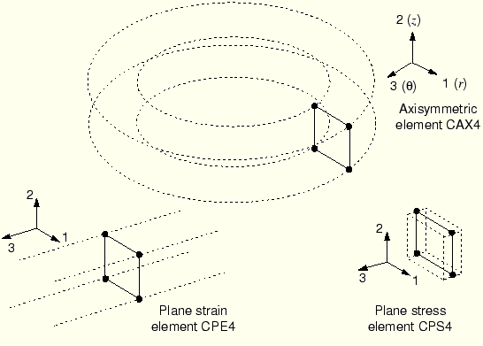
ABAQUS has several classes of two-dimensional continuum elements that differ from each other in their out-of-plane behavior. Two-dimensional elements can be quadrilateral or triangular. Figure 3–3 shows the three classes that are used most commonly.
Plane strain elements assume that the out-of-plane strain, ![]() , is zero; they can be used to model thick structures.
, is zero; they can be used to model thick structures.
Plane stress elements assume that the out-of-plane stress, ![]() , is zero; they are suitable for modeling thin structures.
, is zero; they are suitable for modeling thin structures.
Axisymmetric elements without twist, the “CAX” class of elements, model a 360° ring; they are suitable for analyzing structures with axisymmetric geometry subjected to axisymmetric loading.
ABAQUS/Standard also provides generalized plane strain elements, axisymmetric elements with twist, and axisymmetric elements with asymmetric deformation.
Generalized plane strain elements include the additional generalization that the out-of-plane strain may vary linearly with position in the plane of the model. This formulation is particularly suited to the thermal-stress analysis of thick sections.
Axisymmetric elements with twist model an initially axisymmetric geometry that can twist about the axis of symmetry. These elements are useful for modeling the torsion of cylindrical structures, such as axisymmetric rubber bushings.
Axisymmetric elements with asymmetric deformation model an initially axisymmetric geometry that can deform asymmetrically (typically as a result of bending). They are useful for simulating problems such as an axisymmetric rubber mount that is subjected to shear loads.
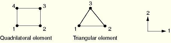
Two-dimensional solid elements must be defined in the 1–2 plane so that the node order is counterclockwise around the element perimeter, as shown in Figure 3–4.
When using a preprocessor to generate the mesh, ensure that the element normals all point in the same direction as the positive, global 3-axis. Failure to provide the correct element connectivity will cause ABAQUS to issue an error message stating that elements have negative area.Degrees of freedom
All of the stress/displacement continuum elements have translational degrees of freedom at each node. Correspondingly, degrees of freedom 1, 2, and 3 are active in three-dimensional elements, while only degrees of freedom 1 and 2 are active in plane strain elements, plane stress elements, and axisymmetric elements without twist. To find the active degrees of freedom in the other classes of two-dimensional solid elements, see “Two-dimensional solid element library,” Section 22.1.3 of the ABAQUS Analysis User's Manual.
Element properties
All solid elements must refer to a solid section property that defines the material and any additional geometric data associated with the element. For three-dimensional and axisymmetric elements no additional geometric information is required: the nodal coordinates completely define the element geometry. For plane stress and plane strain elements the thickness of the elements may be specified or a default value of 1 will be used.
Formulation and integration
Alternative formulations available for the continuum family of elements in ABAQUS/Standard include an incompatible mode formulation (the last or second-to-last letter in the element name is I) and a hybrid element formulation (the last letter in the element name is H), both of which are discussed in detail later in this guide.
In ABAQUS/Standard you can choose between full and reduced integration for quadrilateral and hexahedral (brick) elements. In ABAQUS/Explicit only reduced integration is available for quadrilateral and hexahedral continuum elements. Both the formulation and type of integration can have a significant effect on the accuracy of solid elements, as discussed in “Element formulation and integration,” Section 4.1.
Element output variables
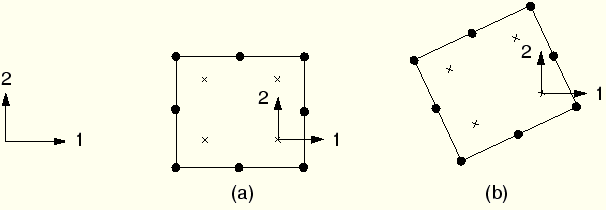
By default, element output variables such as stress and strain refer to the global Cartesian coordinate system. Thus, the ![]() -component of stress at the integration point shown in Figure 3–5(a) acts in the global 1-direction. Even if the element rotates during a large-displacement simulation, as shown in Figure 3–5(b), the default is still to use the global Cartesian system as the basis for defining the element variables.
-component of stress at the integration point shown in Figure 3–5(a) acts in the global 1-direction. Even if the element rotates during a large-displacement simulation, as shown in Figure 3–5(b), the default is still to use the global Cartesian system as the basis for defining the element variables.
Shell elements are used to model structures in which one dimension (the thickness) is significantly smaller than the other dimensions and the stresses in the thickness direction are negligible.
Shell element names in ABAQUS begin with the letter “S.” Axisymmetric shells all begin with the letters “SAX.” ABAQUS/Standard also provides axisymmetric shells with asymmetric deformations, which begin with the letters “SAXA.” The first number in a shell element name indicates the number of nodes in the element, except for the case of axisymmetric shells, for which the first number indicates the order of interpolation.
Two types of shell elements are available in ABAQUS: conventional shell elements and continuum shell elements. Conventional shell elements discretize a reference surface by defining the element's planar dimensions, its surface normal, and its initial curvature. Continuum shell elements, on the other hand, resemble three-dimensional solid elements in that they discretize an entire three-dimensional body yet are formulated so that their kinematic and constitutive behavior is similar to conventional shell elements. In this manual only conventional shell elements are discussed. Henceforth, we will refer to them simply as “shell elements.” For more information on continuum shell elements, see “Shell elements: overview,” Section 23.6.1 of the ABAQUS Analysis User's Manual.
The use of shell elements is discussed in detail in Chapter 5, “Using Shell Elements.”
Shell element library
In ABAQUS/Standard general three-dimensional shell elements are available with three different formulations: general-purpose, thin-only, and thick-only. The general-purpose shells and the axisymmetric shells with asymmetric deformation account for finite membrane strains and arbitrarily large rotations. The three-dimensional “thick” and “thin” element types provide for arbitrarily large rotations but only small strains. The general-purpose shells allow the shell thickness to change with the element deformation. All of the other shell elements assume small strains and no change in shell thickness, even though the element's nodes may undergo finite rotations. Triangular and quadrilateral elements with linear and quadratic interpolation are available. Both linear and quadratic axisymmetric shell elements are available. All of the quadrilateral shell elements (except for S4) and the triangular shell element S3/S3R use reduced integration. The S4 element and the other triangular shell elements use full integration. Table 3–1 summarizes the shell elements available in ABAQUS/Standard.
Table 3–1 Three classes of shell elements in ABAQUS/Standard.
| General-Purpose Shells | Thin-Only Shells | Thick-Only Shells |
|---|---|---|
| S4, S4R, S3/S3R, SAX1, SAX2, SAX2T, SC6R, SC8R | STRI3, STRI65, S4R5, S8R5, S9R5, SAXA | S8R, S8RT |
All the shell elements in ABAQUS/Explicit are general-purpose. Finite membrane strain and small membrane strain formulations are available. Triangular and quadrilateral elements are available with linear interpolation. A linear axisymmetric shell element is also available. Table 3–2 summarizes the shell elements available in ABAQUS/Explicit.
Table 3–2 Two classes of shell elements in ABAQUS/Explicit.
| Finite-Strain Shells | Small-Strain Shells |
|---|---|
| S4R, S3/S3R, SAX1 | S4RS, S4RSW, S3RS |
For most explicit analyses the large-strain shell elements are appropriate. If, however, the analysis involves small membrane strains and arbitrarily large rotations, the small-strain shell elements are more computationally efficient. The S4RS and S3RS elements do not consider warping, while the S4RSW element does.
The shell formulations available in ABAQUS are discussed in detail in Chapter 5, “Using Shell Elements.”
Degrees of freedom
The three-dimensional elements in ABAQUS/Standard whose names end in the number “5” (e.g., S4R5, STRI65) have 5 degrees of freedom at each node: three translations and two in-plane rotations (i.e., no rotations about the shell normal). However, all six degrees of freedom are activated at a node if required; for example, if rotational boundary conditions are applied or if the node is on a fold line of the shell.
The remaining three-dimensional shell elements have six degrees of freedom at each node (three translations and three rotations).
The axisymmetric shells have three degrees of freedom associated with each node:
Element properties
All shell elements must refer to a shell section property that defines the thickness and material properties associated with the element.
The stiffness of the shell cross-section can be calculated either during the analysis or once at the beginning of the analysis.
If you choose to have the stiffness calculated during the analysis, ABAQUS uses numerical integration to calculate the behavior at selected points through the thickness of the shell. These points are called section points, as shown in Figure 3–6. The associated material property definition may be linear or nonlinear. You can specify any odd number of section points through the shell thickness.
If you choose to have the stiffness calculated once at the beginning of the analysis, you can define the cross-section behavior to model linear or nonlinear behavior. In this case ABAQUS models the shell's cross-section behavior directly in terms of section engineering quantities (area, moments of inertia, etc.), so there is no need for ABAQUS to integrate any quantities over the element cross-section. Therefore, this option is less expensive computationally. The response is calculated in terms of force and moment resultants; the stresses and strains are calculated only when they are requested for output. This approach is recommended when the response of the shell is linear elastic.
Element output variables
The element output variables for shells are defined in terms of local material directions that lie on the surface of each shell element. In all large-displacement simulations these axes rotate with the element's deformation. You can also define a local material coordinate system that rotates with the element's deformation in a large-displacement analysis.
Beam elements are used to model components in which one dimension (the length) is significantly greater than the other two dimensions and only the stress in the direction along the axis of the beam is significant.
Beam element names in ABAQUS begin with the letter “B.” The next character indicates the dimensionality of the element: “2” for two-dimensional beams and “3” for three-dimensional beams. The third character indicates the interpolation used: “1” for linear interpolation, “2” for quadratic interpolation, and “3” for cubic interpolation.
The use of beam elements is discussed in Chapter 6, “Using Beam Elements.”
Beam element library
Linear, quadratic, and cubic beams are available in two and three dimensions. Cubic beams are not available in ABAQUS/Explicit.
Degrees of freedom
Three-dimensional beams have six degrees of freedom at each node: three translational degrees of freedom (1–3) and three rotational degrees of freedom (4–6). “Open-section”-type beams (such as B31OS) are available in ABAQUS/Standard and have an additional degree of freedom (7) that represents the warping of the beam cross-section.
Two-dimensional beams have three degrees of freedom at each node: two translational degrees of freedom (1 and 2) and one rotational degree of freedom (6) about the normal to the plane of the model.
Element properties
All beam elements must refer to a beam section property that defines the material associated with the element as well as the beam section profile (i.e., the element's cross-sectional geometry); the nodal coordinates define only the length. You can define the beam section profile geometrically by specifying the shape and dimensions of the section. Alternatively, you can define a generalized beam section profile by specifying the section engineering properties, such as area and moment of inertia.
If you define the beam section profile geometrically, ABAQUS calculates the cross-section behavior of the beam by numerical integration over the cross-section, allowing both linear and nonlinear material behavior.
If you provide the section engineering properties (area, moments of inertia, and torsional constants) instead of the cross-section dimensions, there is no need for ABAQUS to integrate any quantities over the element cross-section. Therefore, this option is less expensive computationally. With this approach, the material behavior may be either linear or nonlinear. The response is calculated in terms of the force and moment resultants; the stresses and strains are calculated only when they are requested for output.
Formulation and integration
The linear beams (B21 and B31) and the quadratic beams (B22 and B32) are shear deformable and account for finite axial strains; therefore, they are suitable for modeling both slender and stout beams. The cubic beam elements in ABAQUS/Standard (B23 and B33) do not account for shear flexibility and assume small axial strain, although large displacements and rotations of the beams are valid. They are, therefore, suitable for modeling slender beams.
ABAQUS/Standard provides variants of linear and quadratic beam elements that are suitable for modeling thin-walled, open-section beams (B31OS and B32OS). These elements correctly model the effects of torsion and warping in open cross-sections, such as I-beams or U-section channels. Open-section beams are not covered in this guide.
ABAQUS/Standard also has hybrid beam elements that are used for modeling very slender members, such as flexible risers on offshore oil installations, or for modeling very stiff links. Hybrid beams are not covered in this guide.
Element output variables
The stress components in three-dimensional, shear-deformable beam elements are the axial stress (![]() ) and the shear stress due to torsion (
) and the shear stress due to torsion (![]() ). The shear stress acts about the section wall in a thin-walled section. Corresponding strain measures are also available. The shear-deformable beams also provide estimates of transverse shear forces on the section. The slender (cubic) beams in ABAQUS/Standard have only the axial variables as output. Open-section beams in space also have only the axial variables as output, since the torsional shear stresses are negligible in this case.
). The shear stress acts about the section wall in a thin-walled section. Corresponding strain measures are also available. The shear-deformable beams also provide estimates of transverse shear forces on the section. The slender (cubic) beams in ABAQUS/Standard have only the axial variables as output. Open-section beams in space also have only the axial variables as output, since the torsional shear stresses are negligible in this case.
All two-dimensional beams use only axial stress and strain.
The axial force, bending moments, and curvatures about the local beam axes can also be requested for output. For details of what components are available with which elements, see “Beam modeling: overview,” Section 23.3.1 of the ABAQUS Analysis User's Manual. Details of how the local beam axes are defined are given in Chapter 6, “Using Beam Elements.”
Truss elements are rods that can carry only tensile or compressive loads. They have no resistance to bending; therefore, they are useful for modeling pin-jointed frames. Moreover, truss elements can be used as an approximation for cables or strings (for example, in a tennis racket). Trusses are also sometimes used to represent reinforcement within other elements. The overhead hoist model in Chapter 2, “ABAQUS Basics,” uses truss elements.
All truss element names begin with the letter “T.” The next two characters indicate the dimensionality of the element—“2D” for two-dimensional trusses and “3D” for three-dimensional trusses. The final character represents the number of nodes in the element.
Truss element library
Linear and quadratic trusses are available in two and three dimensions. Quadratic trusses are not available in ABAQUS/Explicit.
Degrees of freedom
Truss elements have only translational degrees of freedom at each node. Three-dimensional truss elements have degrees of freedom 1, 2, and 3, while two-dimensional truss elements have degrees of freedom 1 and 2.
Element properties
All truss elements must refer to a truss section property that associates a material property definition with the element and specifies its cross-sectional area.
Formulation and integration
In addition to the standard formulation, a hybrid truss element formulation is available in ABAQUS/Standard. It is useful for modeling very stiff links whose stiffness is much greater than that of the overall structure.
Element output variables
Axial stress and strain are available as output for truss elements.